-
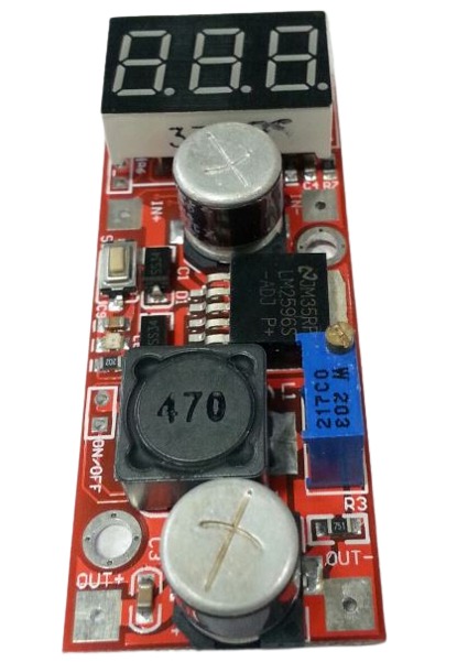 FEATURES: - With voltage meter display,voltage meter error of±0.1V, the range of 0~40V. (note: to ensure that the voltage meter accuracy, please make sure that the input voltage is 4.2V or more). - Low light touch button switch measurement input or output voltage,and a light show is voltage measurement which road, and keep the last set, even if the power switch on again. - Voltmeter fine-tuning: hold down the button about 1-2s into fine-tuning mode, can remove button on the calibration at this time. (please do not use standby function, usually). - Low voltage meter can be closed,long press button closure voltmeter (minimum power loss). - Input voltage:4.2~40v(input voltage must be higher than to the output voltage of more than 1v). - Output voltage adjustable range1.25V~37V adjustable (input voltage must be higher than to the output voltage is more than 1V).
 -
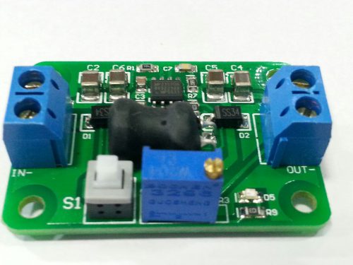
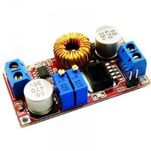
Specification Input voltage range: 5~24V; Output voltage range: 0.93V~18V Features DC-DC adjustable step-down module Application Various electronic products or DIY projects English Manual/Spec Yes Other Input voltage range: 5~24V; Output voltage range: 0.93~18V (buck mode, enter at least greater than the output 2V above); Output current: 2.5A; Output peak 4A continuous output; Switch: With soft-off feature; Shutdown current low microampere level; Size: 45mm x 32mm x 16mm; Technical description: Measured efficiency: 12V converts to 5V: 12V converts to 5V efficiency = (5V x 1.001A) / (12V x 0.431) = 96.7%; 18V converts to 12V: 18V to 12V Efficiency = (12.019V x 1.001A) / (18.01V x 0.679) = 98.38% -
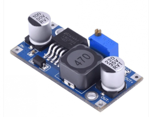
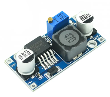
- Input: DC 3V to 40V (input voltage must be higher than the output voltage to 1.5v above can not boost)
- Output: DC 1.5V to 35V voltage continuously adjustable, high-efficiency maximum output current of 3A.
- Features: All solid capacitors, the 36u thickening circuit boards, high-Q inductance with output value of high-power LED indicator
- Dimensions: 45 (L) * 20 (W) * 14 (H) mm (with potentiometer)
-
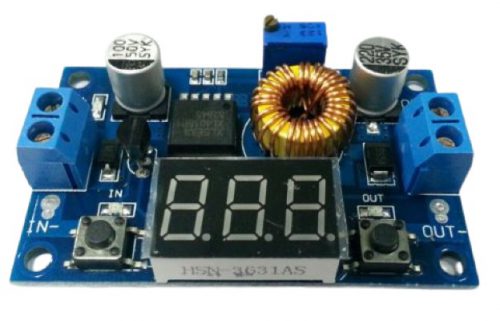 Module feature and performance: 5A high-power and high efficiency reduction voltage and low ripple High quality and good performance With power light and voltage display with self-correcting. Adopting advanced voltage microprocessor, and the voltmeter error ±0.1V, measuring range is 0~40V (Note: Please make sure input voltage more than 3.5V to make the voltmeter normal working) Touch the button to change input or output voltage, LED indicator light display is measuring voltage, and can autosave which one voltage, keep pressing the key can turn off the voltmeter Input voltage 4.0~38V (the input voltage must be higher 1.5V than output voltage) Adjustable output voltage range: 1.25V~36V (the input voltage must be higher 1.5V than output voltage) Output power can reach 75W. Output current can reach 5A, suggested use it less than 4.5A (note: Please add a cooling fin into power chip, if you use it with high-power)
 -
 1. 10 DOF Module (3 axis gyroscope 3 accelerometer 3 axis magnetic field air pressure) 2. Technology:Immersion Gold PCB 3. Chip: MPU6050 HMC5883L MS5611 4.Power Supply :3-5v 5.Communication: IIC communication protocol (fully compatible with the 3-5v System, circuit LLC is contained ) 6.Size: 2.2cm * 1.7cm
 -
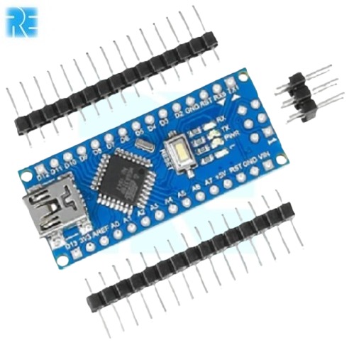
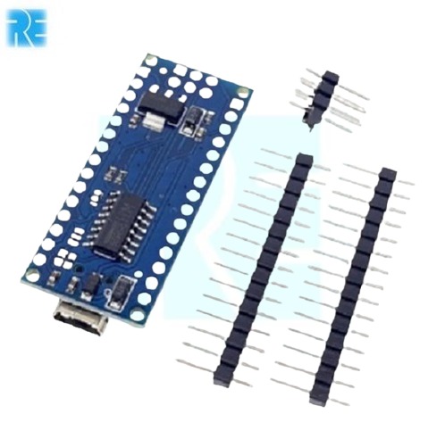 Arduino Nano is a surface mount breadboard embedded version with integrated USB. It is a smallest, complete, and breadboard friendly. It has everything that Diecimila/Duemilanove has (electrically) with more analog input pins and onboard 5V AREF jumper. Physically, it is missing power jack. The Nano is automatically sense and switch to the higher potential source of power, there is no need for the power select jumper. Nano’s got the breadboard-ability of the Boarduino and the Mini USB with smaller footprint than either, so users have more breadboard space. It’s got a pin layout that works well with the Mini or the Basic Stamp (TX, RX, ATN, GND on one top, power and ground on the other). This new version 3.0 comes with ATMEGA328 which offer more programming and data memory space. It is two layers. That make it easier to hack and more affordable.
 -
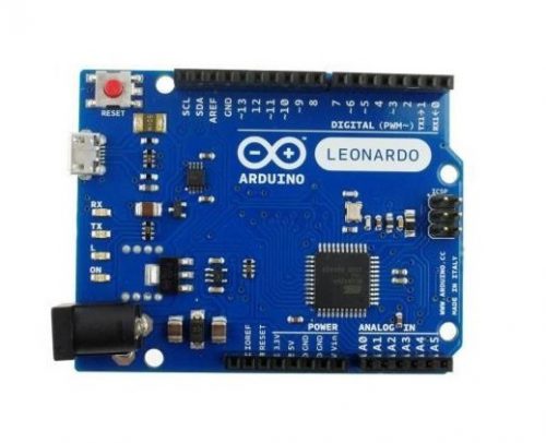 The Leonardo is Arduino’s first development board to use one microcontroller with built-in USB. Using the ATmega32U4 as its sole microcontroller allows it to be cheaper and simpler. Also, because the 32U4 is handling the USB directly, code libraries are available which allow the board to emulate a computer keyboard, mouse, and more using the USB-HID protocol! It has 20 digital input/output pins (of which 7 can be used as PWM outputs and 12 as analog inputs), a 16 MHz crystal oscillator, a micro USB connection, a power jack, an ICSP header, and a reset button. It contains everything needed to support the microcontroller; simply connect it to a computer with a USB cable or power it with a AC-to-DC adapter or battery to get started.
 -
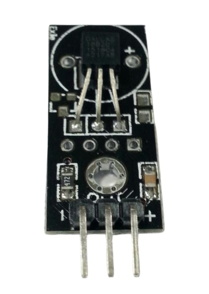 Introduction: These 3-wire digital temperature sensors are fairly precise (±0.5°C over much of the range) and can give up to 12 bits of precision from the onboard digital-to-analog converter. They work great with any microcontroller using a single digital pin, and you can even connect multiple ones to the same pin, each one has a unique 64-bit ID burned in at the factory to differentiate them. Usable with 3.0-5.0V systems. Technical Details: Technical specs: Usable temperature range: -5° to 90°C (-23°F to 194°F) 9 to 12 bit selectable resolution Uses 1-Wire interface- requires only one digital pin for communication Unique 64 bit ID burned into chip Multiple sensors can share one pin ±0.5°C Accuracy from -10°C to 85°C Temperature-limit alarm system Query time is less than 750ms Usable with 3.0V to 5.5V power/data
 -
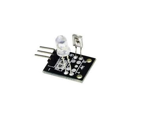 The Keyes-039 or KY039 Heart rate monitor consists of two things, an Infrared LED, and an Infrared Phototransistor. The IR LED should come on whenever the sensor has power and stay on (because it is infrared, you won’t be able to see that it is on, but if you look through your cell phone camera you will). The IR photo transistor causes the voltage to change on a “sensor” wire, and this should be connected to one of the Arduino’s analog pins.

YOUR PARTNER IN TECHNOLOGY SOLUTIONS
YOUR PARTNER IN TECHNOLOGY SOLUTIONS
No.1030, Shriram Building,
Near Nagnath Par,
Sadashiv Peth, Pune – 411030,
Maharashtra, India
![]() Visit Our store
Visit Our store
STORE TIMINGS
Monday to Saturday
10:00 AM to 7.30 PM
(Store closed on all Sundays and Public Holidays)
NOTE
*All the prices are excluding Tax rates & are subject to change after a specific period of time.
Copyright © 2024@AbhinavDCS