-
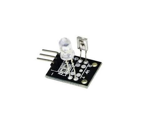
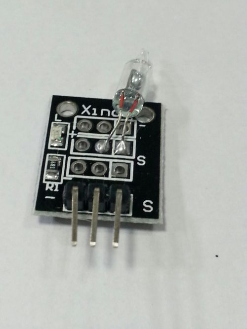 The KY017 is a mercury tilt switch that allows you to detect the tilt of your object so that you can take the appropriate action. It is a nice low cost alternative to a 6 axis accelerometer. When strategically adjusted or situated, it can be very sensitive. The key to using this switch successfully is in understanding the two operational states.
 -
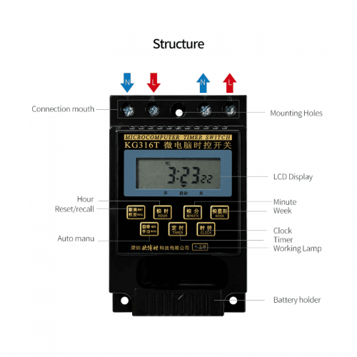
Programmable Number: 8 Group / 16 Group
Output Mode: 1 Constant Open Contact
Time Control Range: 1 min to 168 hours
Operation Modes: Manual, Automatic
# Image shown is a representation only #
-
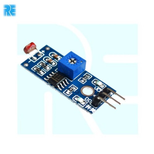
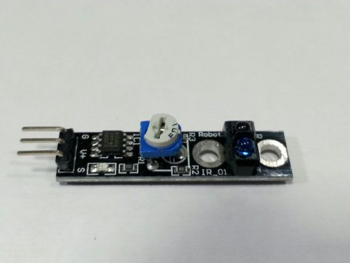 Description: -Brand new Black/White Line Hunting Sensor for Intelligent Car Tracing. -Features VCC/OUT/GND pin connector. -Output electrical level signal: Low level when detecting objects/ high level when no objects/0 or 1 decides if objects exist. -Power by 2.5-12V (cannot over 12V). -Perfect DIY parts for intelligent cars. -Color: Black panel -Working Current: 18-20mA at 5V -Package Dimensions: 77.0 x 49.0 x 12.0 mm -Weight: 5.0g
 -
 The Keyes-039 or KY039 Heart rate monitor consists of two things, an Infrared LED, and an Infrared Phototransistor. The IR LED should come on whenever the sensor has power and stay on (because it is infrared, you won’t be able to see that it is on, but if you look through your cell phone camera you will). The IR photo transistor causes the voltage to change on a “sensor” wire, and this should be connected to one of the Arduino’s analog pins.
 -
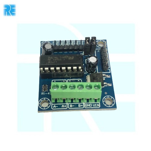
 L293D 4 Channel DC Motor Driver E-4 Operating Voltage(VDC): 4.5 to 12 Peak Current (A): 600 Ma Motor Voltage supply: 9-12V
 -
 L293D Motor Driver Board E-40 L293D Motor Driver shield Input Voltage Range: 4.5 To 24VDC Output current Per Channel: 600mA Peak Output current: 1.2A
 -
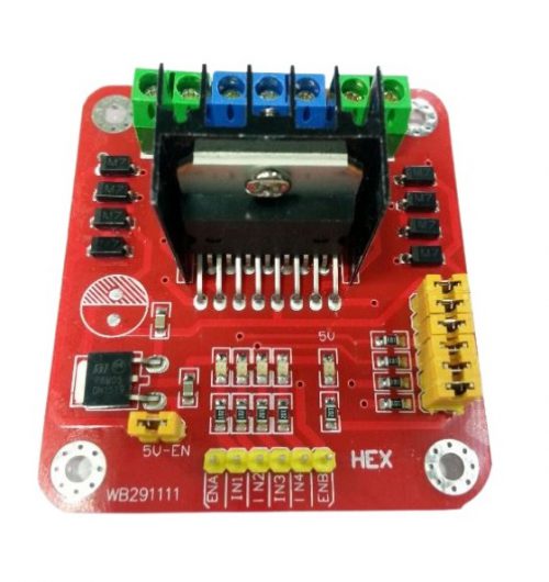
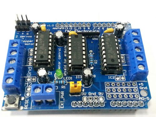 The Arduino Motor Shield is based on the L298, which is a dual full-bridge driver designed to drive inductive loads such as relays, solenoids, DC and stepping motors. It lets you drive two DC motors with your Arduino board, controlling the speed and direction of each one independently. You can also measure the motor current absorption of each motor, among other features.
 -
- Drive a 2-phase bipolar stepper motor or two DC motors with the L298 dual H-Bridge chip, mounted on this handy breakout board along with all necessary peripherals!
- It is ideal for robotic applications and well suited for connection to a microcontroller requiring just a couple of control lines per motor. It can also be interfaced with simple manual switches, TTL logic gates, relays, etc.
-
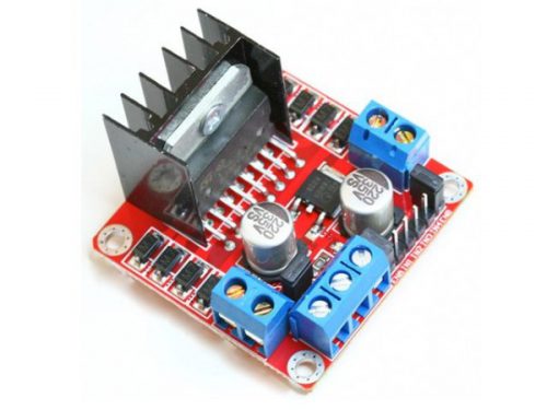
 This module is based on the very popular L298 Dual H-Bridge Motor Driver Integrated Circuit. The circuit will allow you to easily and independently control two motors of up to 2A each in both directions. It is ideal for robotic applications and well suited for connection to a microcontroller requiring just a couple of control lines per motor. It can also be interfaced with simple manual switches, TTL logic gates, relays, etc.
Features
- Motor supply : 7 to 24 VDC
- Control Logic : Standard TTL Logic Level
- Output Power : Up to 2 A each
- Enable and Direction Control Pins
- Heatsink for IC
- Power-On LED indicator
- 4 Direction LED indicators
Specifications
- Module Type Driver
- Weight : 35.00g
- Board Size : 5.5 x 5 x 2.9cm
- Version : 1
- Operation Level : Digital 5V
- Power Supply : External 12V
- External : 7V
- External : 9V
-
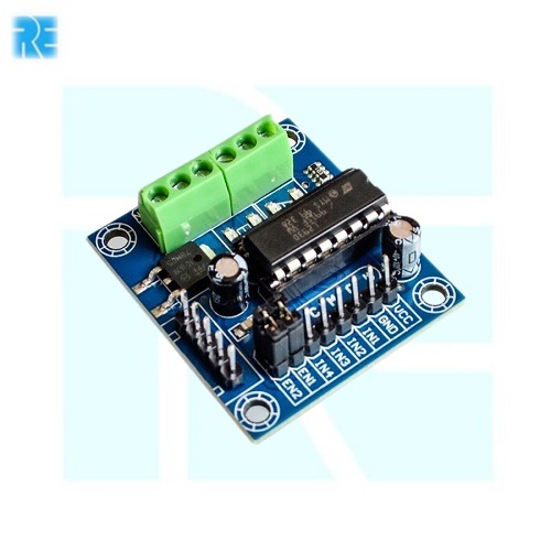
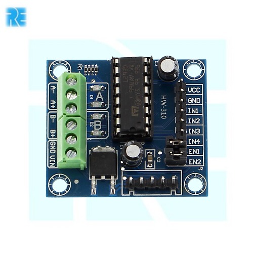
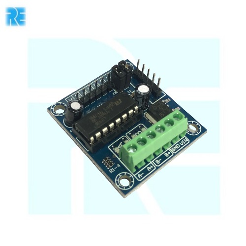
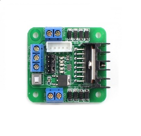
 L298N driver module, using ST's L298N chip can directly drive two 3-30V DC motor, and provides a 5V output interface can 5V single-chip circuitry to supply, support 3.3VMCU control, you can easily control the DC motor speed and direction, you can also control the 2-phase stepper motor, smart car is essential.
 -
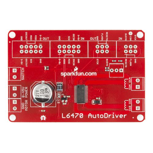 L6470 is a 3A, 8-45V bipolar stepper motor driver. It has built-in overcurrent detection, undervoltage detection, overtemperature detection, stall detection, a 5-bit ADC, and a switch input that can be used for either user jog control or as a hard stop function. As if that weren’t enough, it also features microstepping support (up to 128 microsteps per full step) and PWM drive voltage limiting. The logic supply voltage supports both 3.3V and 5V I/O levels.
 -
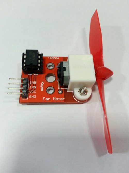 Features: *Size: 50 x 26 x 15mm (excluding propellers) *Propeller diameter: 75mm *Operating voltage: 5V *L9110 driver can control reversing, with mounting holes, compatible steering rudder control, quality and high efficiency propeller. *Can easily blow out the flame lighters 20m away, can be used for fire fighting robot, it is essential for robot design and development.
 -

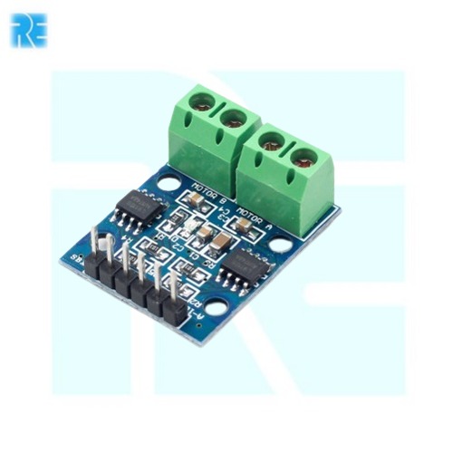 L9110 chip is able to drive a single DC motor using two digital control inputs. One input is used to select the motor direction while the other is used to control the motor speed. Speed is controlled by using PWM Pulse Width Modulation. Motor drivers typically have what is called a truth table that determines the effect of its inputs.
 -
 The LilyPad Arduino consists of an ATmega328 with the Arduino bootloader and a minimum number of external components to keep it as small (and as simple) as possible. This board will run from 2V to 5V and offers large pin-out holes that make it easy to sew and connect. Each of these pins, with the exception of ( ) and (-), can control an attached input or output device (like a light, motor, or switch).
 -
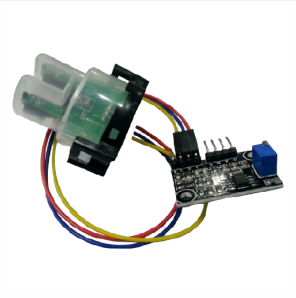
 *Heating voltage: 5 ± 0.2V (AC · DC). *Current :5-10mA. *Detectable concentration range: PH0-14. *Test the temperature range :0-80 °. *Response time: ≤ 5S. *Stabilization time: ≤ 60S. *Component Power: ≤ 0.5W. *Working temperature: -10 ~ 50 ° (nominal temperature 20 °). *Humidity: 95% RH (nominal humidity 65% RH). *Life: 3 years. *Size: 42mm × 32mm × 20mm.
 -
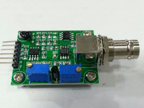
 Introduction: The turbidity sensor detects water quality by measuring the levels of turbidity. It uses light to detect suspended particles in water by measuring the light transmittance and scattering rate, which changes with the amount of total suspended solids (TSS) in water. As the TTS increases, the liquid turbidity level increases. Turbidity sensors are used to measure water quality in rivers and streams, wastewater and effluent measurements, control instrumentation for settling ponds, sediment transport research and laboratory measurements. Specification:
- Operating Voltage: 5V DC
- Operating Current: 40mA (MAX)
- Response Time : <500ms
- Insulation Resistance: 100M (Min)
- Output Method:
- Analog output: 0-4.5V
- Digital Output: High/Low level signal (you can adjust the threshold value by adjusting the potentiometer)
- Operating Temperature: 5℃~90℃
- Storage Temperature: -10℃~90℃
- Weight: 30g
- Adapter Dimensions: 38mm*28mm*10mm/1.5inches *1.1inches*0.4inches
-
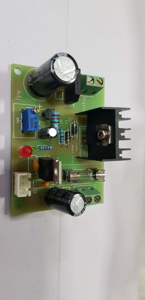
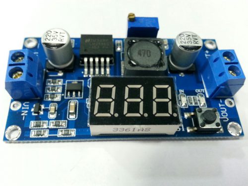 Features 1 Input voltage range:4 -40VDC 2 Output voltage range:1.25-37VDC adjustable 3 Output current:2A 4 voltmeter range: 0 to 40V, error 0.1V 5 Input reverse polarity protection 6 Built in output short protection function 7 Built in thermal shutdown function 8 L x W x H =6.1*3.4*12 cm 9 Weight: 22g 10 LED digital voltmeter tube, the accuracy is adjustable function, can be aimed at your multimeteradjustable accurate. 11 Press the rightkey to let the display show the input or output voltage. when the right OUT led light, it shows output, the left IN led show input.
 -
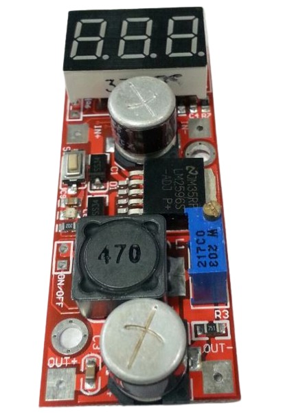 FEATURES: - With voltage meter display,voltage meter error of±0.1V, the range of 0~40V. (note: to ensure that the voltage meter accuracy, please make sure that the input voltage is 4.2V or more). - Low light touch button switch measurement input or output voltage,and a light show is voltage measurement which road, and keep the last set, even if the power switch on again. - Voltmeter fine-tuning: hold down the button about 1-2s into fine-tuning mode, can remove button on the calibration at this time. (please do not use standby function, usually). - Low voltage meter can be closed,long press button closure voltmeter (minimum power loss). - Input voltage:4.2~40v(input voltage must be higher than to the output voltage of more than 1v). - Output voltage adjustable range1.25V~37V adjustable (input voltage must be higher than to the output voltage is more than 1V).
 -
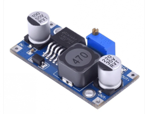
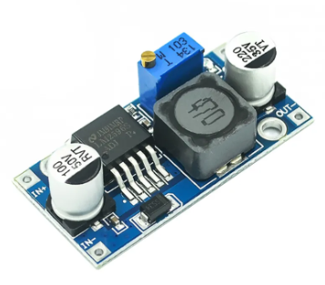
- Input: DC 3V to 40V (input voltage must be higher than the output voltage to 1.5v above can not boost)
- Output: DC 1.5V to 35V voltage continuously adjustable, high-efficiency maximum output current of 3A.
- Features: All solid capacitors, the 36u thickening circuit boards, high-Q inductance with output value of high-power LED indicator
- Dimensions: 45 (L) * 20 (W) * 14 (H) mm (with potentiometer)

YOUR PARTNER IN TECHNOLOGY SOLUTIONS
YOUR PARTNER IN TECHNOLOGY SOLUTIONS

No.1030, Shriram Building,
Near Nagnath Par,
Sadashiv Peth, Pune – 411030,
Maharashtra, India
![]() Visit Our store
Visit Our store
STORE TIMINGS
Monday to Saturday
10:00 AM to 7.30 PM
(Store closed on all Sundays and Public Holidays)
NOTE
*All the prices are excluding Tax rates & are subject to change after a specific period of time.
Copyright © 2024@AbhinavDCS