-
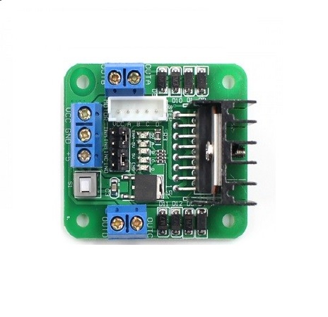 This module is based on the very popular L298 Dual H-Bridge Motor Driver Integrated Circuit. The circuit will allow you to easily and independently control two motors of up to 2A each in both directions. It is ideal for robotic applications and well suited for connection to a microcontroller requiring just a couple of control lines per motor. It can also be interfaced with simple manual switches, TTL logic gates, relays, etc.
Features
- Motor supply : 7 to 24 VDC
- Control Logic : Standard TTL Logic Level
- Output Power : Up to 2 A each
- Enable and Direction Control Pins
- Heatsink for IC
- Power-On LED indicator
- 4 Direction LED indicators
Specifications
- Module Type Driver
- Weight : 35.00g
- Board Size : 5.5 x 5 x 2.9cm
- Version : 1
- Operation Level : Digital 5V
- Power Supply : External 12V
- External : 7V
- External : 9V
-
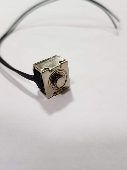
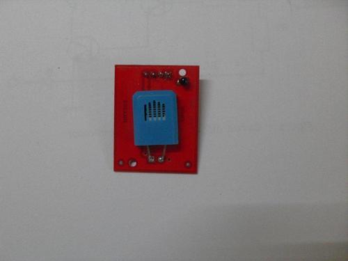
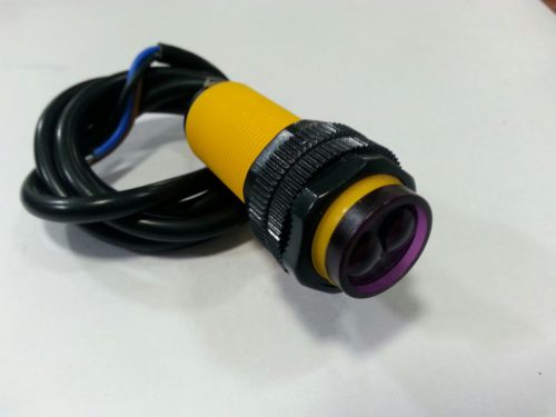 This sensor takes a continuous reading of any obstacle and settles it at output in TTL form within 2ms. The sensor provides easy interface of 3-wire with power, ground and the output voltage. The sensor works on 5V input Features -Very Small in size -Less influence on the color of reflected objects, reflectivity -Industrial grade quality -Can detect colour difference from certain range -TTL output high whenever sensor senses a obstacle -Detecting distance of 3cm to 80cm -External control circuit unnecessary -Low cost -Has inbuilt lenses assembly and potentiometer to set range of the module -Output indication LED
 -
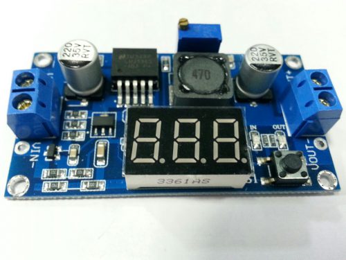 Features 1 Input voltage range:4 -40VDC 2 Output voltage range:1.25-37VDC adjustable 3 Output current:2A 4 voltmeter range: 0 to 40V, error 0.1V 5 Input reverse polarity protection 6 Built in output short protection function 7 Built in thermal shutdown function 8 L x W x H =6.1*3.4*12 cm 9 Weight: 22g 10 LED digital voltmeter tube, the accuracy is adjustable function, can be aimed at your multimeteradjustable accurate. 11 Press the rightkey to let the display show the input or output voltage. when the right OUT led light, it shows output, the left IN led show input.
 -
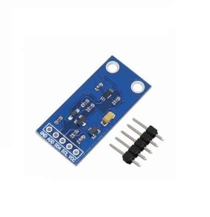
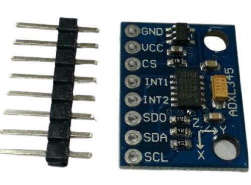 This new version adds 2 standoff holes as well as an extra decoupling capacitor. The ADXL345 is a small, thin, low power, 3-axis MEMS accelerometer with high resolution (13-bit) measurement at up to -16 g. Digital output data is formatted as 16-bit twos complement and is accessible through either a SPI (3- or 4-wire) or I2C digital interface. The ADXL345 is well suited to measures the static acceleration of gravity in tilt-sensing applications, as well as dynamic acceleration resulting from motion or shock. Its high resolution (4 mg/LSB) enables measurement of inclination changes less than 1.0 degrees;.
 -
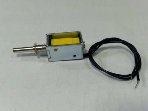
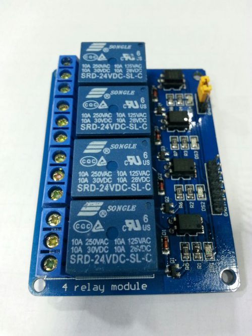 '-24V 4-Channel Relay interface board, and each one needs 50-60mA Driver Current. -Equipped with high-current relay, AC250V 10A ; DC30V 10A. -Standard interface that can be controlled directly by microcontroller (Arduino , 8051, AVR, PIC, DSP, ARM, ARM, MSP430, TTL logic). -Indication LED’s for Relay output status.
 -
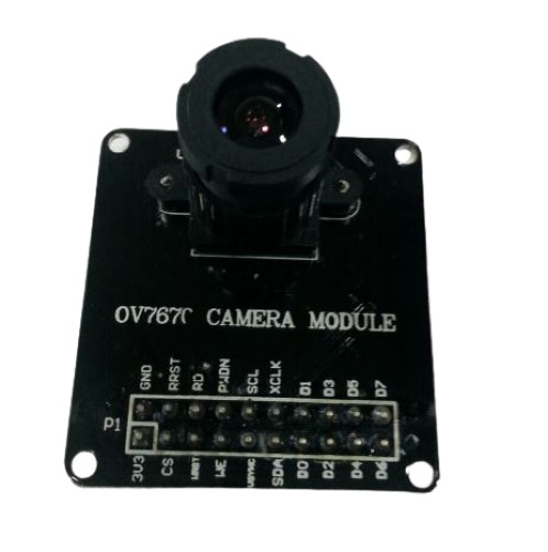 The OV7670 is a low cost image sensor DSP that can operate at a maximum of 30 fps and 640 x 480 ("VGA") resolutions, equivalent to 0.3 Megapixels. The captured image can be pre-processed by the DSP before sending it out. This preprocessing can be configured via the Serial Camera Control Bus (SCCB).

YOUR PARTNER IN TECHNOLOGY SOLUTIONS
YOUR PARTNER IN TECHNOLOGY SOLUTIONS


No.1030, Shriram Building,
Near Nagnath Par,
Sadashiv Peth, Pune – 411030,
Maharashtra, India
![]() Visit Our store
Visit Our store
STORE TIMINGS
Monday to Saturday
10:00 AM to 7.30 PM
(Store closed on all Sundays and Public Holidays)
NOTE
*All the prices are excluding Tax rates & are subject to change after a specific period of time.
Copyright © 2024@AbhinavDCS