-
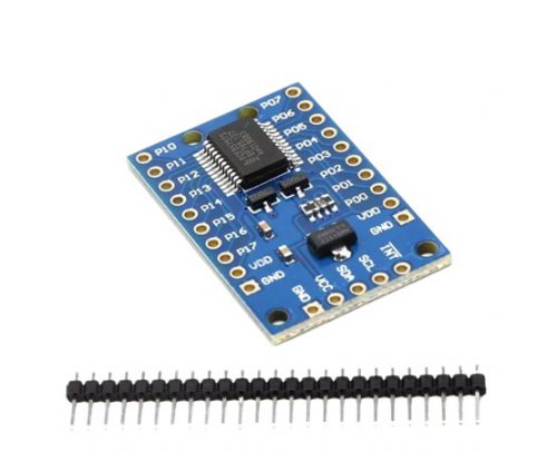
 Description: The module is used in chip TM1638, a collection of these three common MCU peripheral circuit, the biggest feature is just take three microcontroller IO port to drive, do not need to scan display and key scanning microcontroller intervention, only need to read the relevant register send display data or test button, save MCU resources. We usually use an external microcontroller 8 LED, 8 digital tube, eight keys which will occupy the number of IO ports, far more than three IO mouth it, but with this module can be achieved. The practical application of key sensitive display good results. Wiring: VCC GND connected to 5V power supply, STB CLK DIO connected microcontroller IO port.
 -
 - The item is a 5V 1-channel relay interface board and it can be controlled directly by a wide range of microcontrollers such as Arduino, AVR, PIC, ARM and so on. - 1-Channel Relay interface board - Equipped with high-current relay : DC 30V, AC 250V, 30A - Standard interface that can be controlled directly by microcontroller (Arduino, 8051, AVR, PIC, DSP, ARM)Dimensions: 1.85 in x 1.46 in x 0.83 in (4.7 cm x 3.7 cm x 2.1 cm) Weight: 1.16 oz (33 g)
 -
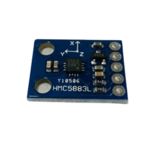 Magnetic fields and current go hand-in-hand. When current flows through a wire, a magnetic field is created. This is the basic principle behind electromagnets. This is also the principle used to measure magnetic fields with a magnetometer. The direction of Earth's magnetic fields affects the flow of electrons in the sensor, and those changes in current can be measured and calculated to derive a compass heading or other useful information
 -
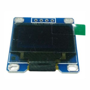 hese displays are small, only about 1" diameter, but very readable due to the high contrast of an OLED display. This display is made of 128x64 individual white OLED pixels, each one is turned on or off by the controller chip. Because the display makes its own light, no backlight is required. This reduces the power required to run the OLED and is why the display has such high contrast; we really like this miniature display for its crispness!
 -
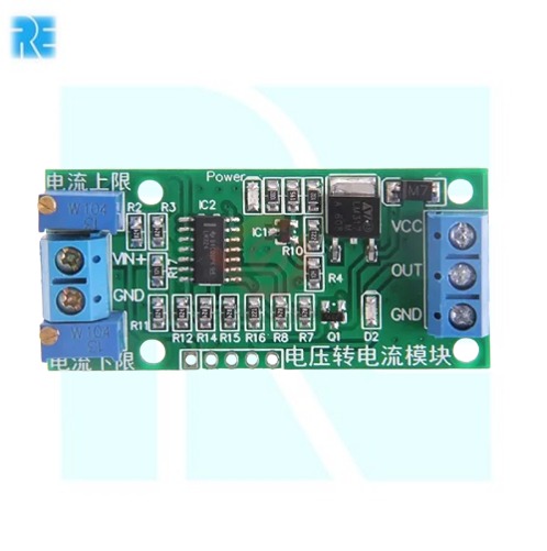
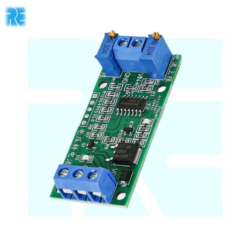 Voltage to Current Module 0-15V to 4-20mA Current Transmitter E-865 Supply Voltage range : 7-30vdc Wide input range : 0-2.5V. Industry-standard 4-20mA current output.
 -
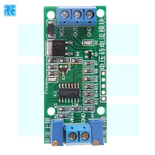 Voltage to Current Module 0-10V to 4-20mA Current Transmitter E-864 Supply Voltage range : 7-30vdc Wide input range : 0-2.5V. Industry-standard 4-20mA current output
 -
 Voltage to Current Module 0-5V to 4-20mA Current Transmitter E-863 Supply Voltage range : 7-30vdc Wide input range : 0-2.5V. Industry-standard 4-20mA current output.
 -
 Operating voltage- 2.5-5.5VDC Operating current- 100mA (max) I2C address- 0x20 (default) can be changed by soldering A1 and selection pads A2
# Image shown is a representation only #
-
 This breakout board for TI’s DRV8825 micro stepping bipolar stepper motor driver features adjustable current limiting, over-current and over-temperature protection, and six microstep resolutions (down to 1/32-step). It operates from 8.2 V to 45 V and can deliver up to approximately 1.5 A per phase without a heat sink or forced air flow (rated for up to 2.2 A per coil with sufficient additional cooling). The driver has a pinout and interface that are nearly identical to those of our A4988 stepper motor driver carriers, so it can be used as a higher-performance drop-in replacement for those boards in many applications.
 -
Product Description:
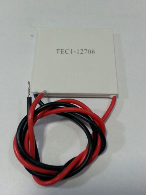
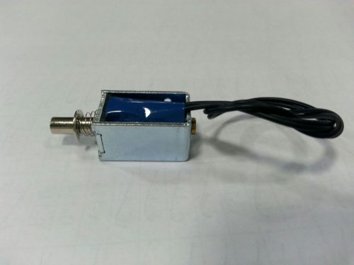
Keep it cool with a Peltier module Thermoelectric Cooler . These unique electronic components can generate a temperature differential when powered. That is to say, apply 12V to the red (positive) and black (negative) wires and one side will get cold while the other side gets hot. For best results, you'll need to wick away that heat (otherwise the cold side will slowly get warmer). A fan and/or heatsink is ideal. This module is a 12V module, and is rated for ~72W max (up to 14V/6A) but when used with a regulated 12V output they don't draw more than 5A so we suggest our 12V/5A power adapter for use. -
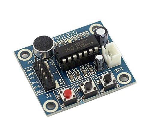
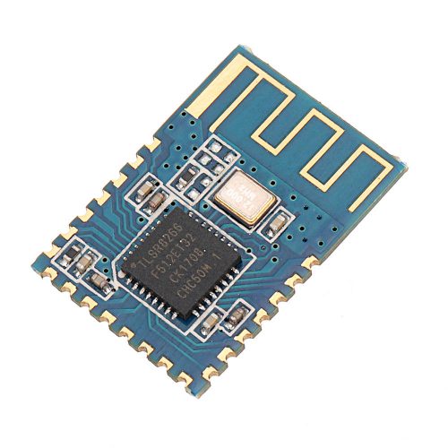
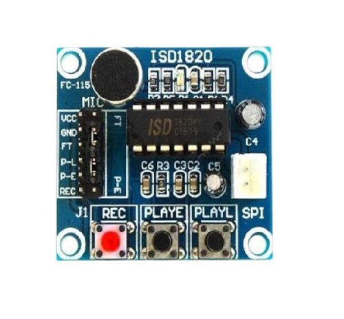 ISD1820 chipset - On board microphone for directly recording - Supports up to around 10 seconds - High-quality, natural voice restored, can be used as a loudspeaker module - Loop playback, jog playback, single-pass playback - All main pins are lead out, allows to operate with microcontroller - Working voltage: 3~5V
 -
 5 Channel Tracking IR Sensor Array Module Board Trace Module Infrared Detection.
- 5 channel high sensitivity sensor
- High accuracy for tracking black line.
- Distance sensor at the front, distance can be adjusted
- Special touch sensor design, making the robot design simple
- Digital output signal
- Indicator LEDs
- Detection distance: 0 - 4cm (black and white line sensors), 0 - 5cm (adjustable distance detection)
- Input voltage: 3.0V - 5.5V
-
 Cable Length - 19CM Each wire has a clip on one end to make it simple and safe to clip and unclip the test points on you
# Image shown is a representation only #
-
# Image shown is a representation only #
-
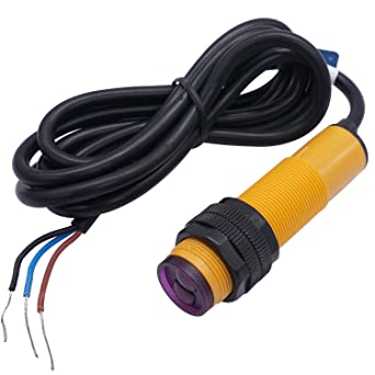
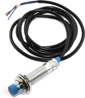
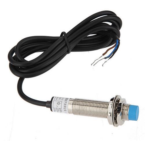
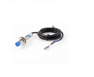 Output Type: PNP-NO Outer (Thread) Diameter: M12 Antivibration, dust, water and oil prevention
# Image shown is a representation only #
-
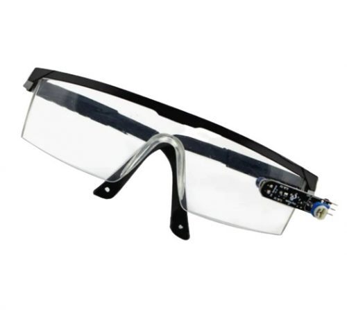
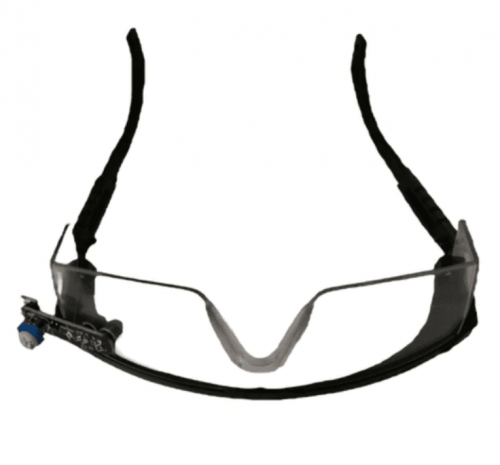 # Image shown is a representation only # Working Voltage +5V DC TTL output 5V or 0V EYE BLINK indication by LED
 -
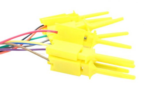
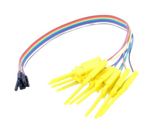
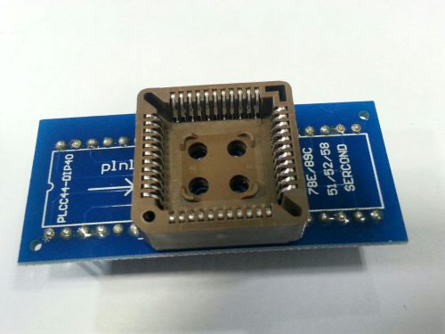
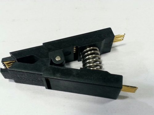 This is an IC Test Clip for 8-pin small outline integrated circuits (SOIC). This test clip assures a secure connection to all chip leads on an 8-pin SMD SOIC and provides hands-free testing. On this test clip you will find two sets of gold plated contacts, upper contacts to attach wiring and lower contacts for an 8-pin IC. Simply place your choice of IC in the lower contacts and attach female terminated jumper wires to the 0.1" spaced upper contacts and you are ready to start testing!
 -
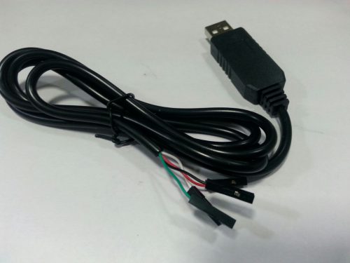 The cable is easiest way ever to connect to your microcontroller/Raspberry Pi/WiFi router serial console port. Inside the big USB plug is a USB<->Serial conversion chip and at the end of the 36" cable are four wire - red power, black ground, white RX into USB port, and green TX out of the USB port. The power pin provides the 5V @ 500mA direct from the USB port and the RX/TX pins are 3.3V level for interfacing with the most common 3.3V logic level chip-sets.
 -
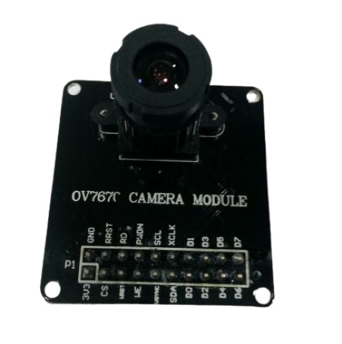 The OV7670 is a low cost image sensor DSP that can operate at a maximum of 30 fps and 640 x 480 ("VGA") resolutions, equivalent to 0.3 Megapixels. The captured image can be pre-processed by the DSP before sending it out. This preprocessing can be configured via the Serial Camera Control Bus (SCCB).

YOUR PARTNER IN TECHNOLOGY SOLUTIONS
YOUR PARTNER IN TECHNOLOGY SOLUTIONS

No.1030, Shriram Building,
Near Nagnath Par,
Sadashiv Peth, Pune – 411030,
Maharashtra, India
![]() Visit Our store
Visit Our store
STORE TIMINGS
Monday to Saturday
10:00 AM to 7.30 PM
(Store closed on all Sundays and Public Holidays)
NOTE
*All the prices are excluding Tax rates & are subject to change after a specific period of time.
Copyright © 2024@AbhinavDCS