-
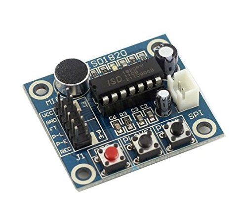
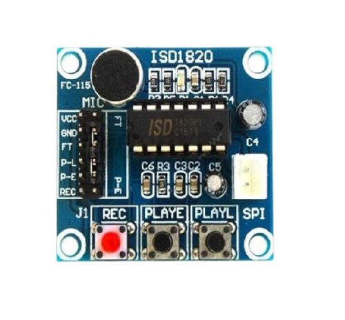 ISD1820 chipset - On board microphone for directly recording - Supports up to around 10 seconds - High-quality, natural voice restored, can be used as a loudspeaker module - Loop playback, jog playback, single-pass playback - All main pins are lead out, allows to operate with microcontroller - Working voltage: 3~5V
 -
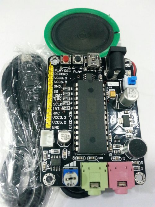 It is the Third recording module developed , this version is distinctly improved in the acoustic fidelity relative to the first and second version.
- Built-in microcontroller serial communication interface
- 3V single-supply operation, low power consumption
- Multi-information processing
- Working current 25-30mA, to maintain current 1μA
- Information is not power to save 100 years (typical)
- High-quality, natural voice reduction technology
- 10 million times the recording period (typical)
- Automatic squelch
- Free adjustment of the clock chip, the external clock can be selected
-
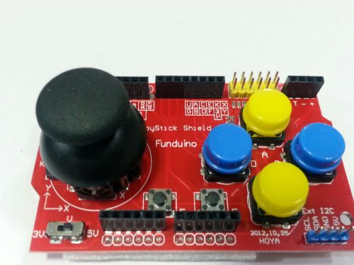 Description: Here we have a Joystick shield that sits atop your Arduino and turns it into a simple controller. 7 momentary push buttons (4 big buttons, 2 small buttons, and a joystick select button) and a two-axis thumb joystick gives your Arduino functionality on the level of the old Nintendo controllers.
 -
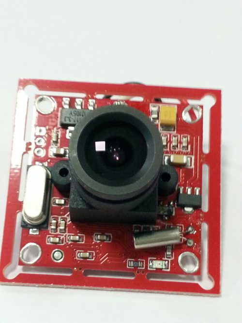 This is a simple-to-use, UART controlled, color camera with on-board JPEG compression. Capable of resolutions up to 640x480, and a number of color types. Send the snapshot command, and this module will capture a single-frame picture, compress it, and send it back over a serial connection.
 -

# Image shown is a representation only #
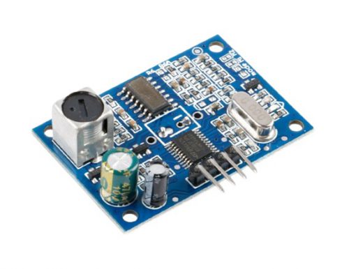
Working voltage : DC 5V Acoustic emission frequency : 40KHz Wiring : +5V (positive) Trig-(control) Echo-(receive) GND-(cathode) -
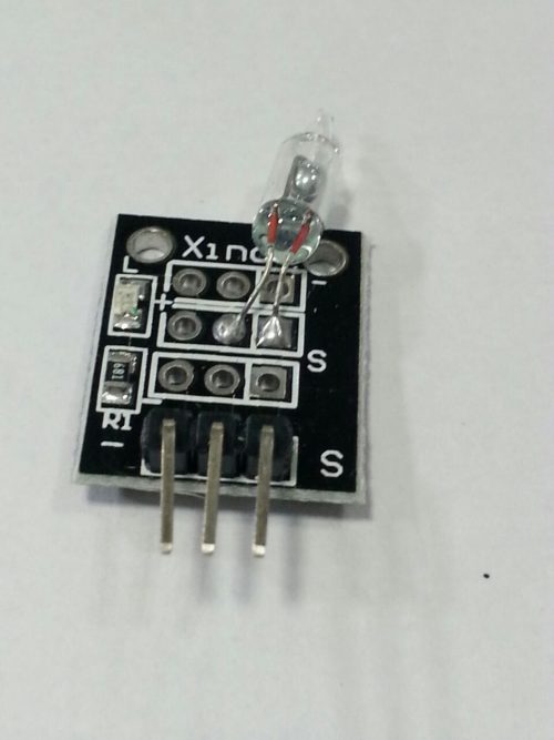 The KY017 is a mercury tilt switch that allows you to detect the tilt of your object so that you can take the appropriate action. It is a nice low cost alternative to a 6 axis accelerometer. When strategically adjusted or situated, it can be very sensitive. The key to using this switch successfully is in understanding the two operational states.
 -
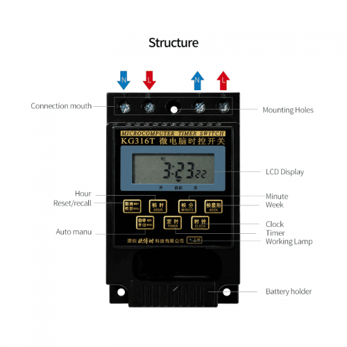
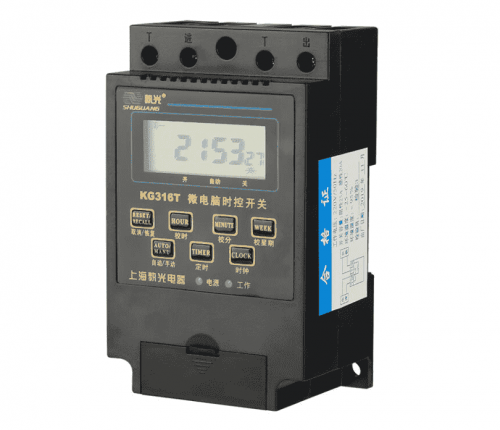
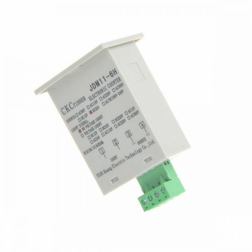
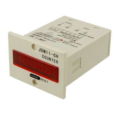
Programmable Number: 8 Group / 16 Group
Output Mode: 1 Constant Open Contact
Time Control Range: 1 min to 168 hours
Operation Modes: Manual, Automatic
# Image shown is a representation only #
-
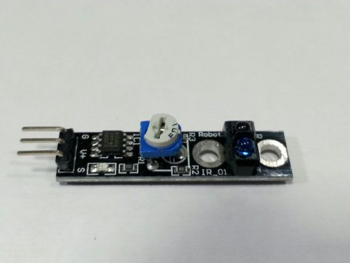 Description: -Brand new Black/White Line Hunting Sensor for Intelligent Car Tracing. -Features VCC/OUT/GND pin connector. -Output electrical level signal: Low level when detecting objects/ high level when no objects/0 or 1 decides if objects exist. -Power by 2.5-12V (cannot over 12V). -Perfect DIY parts for intelligent cars. -Color: Black panel -Working Current: 18-20mA at 5V -Package Dimensions: 77.0 x 49.0 x 12.0 mm -Weight: 5.0g
 -
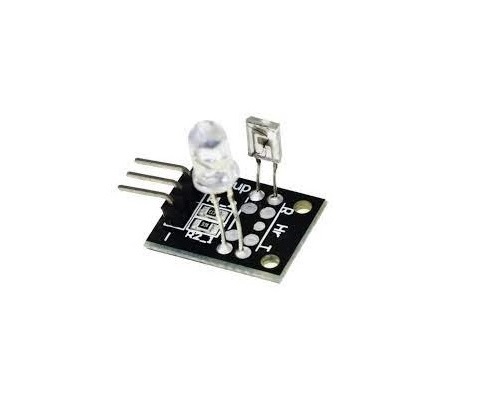 The Keyes-039 or KY039 Heart rate monitor consists of two things, an Infrared LED, and an Infrared Phototransistor. The IR LED should come on whenever the sensor has power and stay on (because it is infrared, you won’t be able to see that it is on, but if you look through your cell phone camera you will). The IR photo transistor causes the voltage to change on a “sensor” wire, and this should be connected to one of the Arduino’s analog pins.
 -
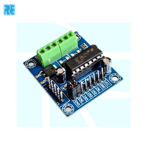
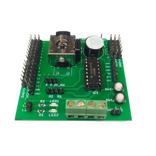
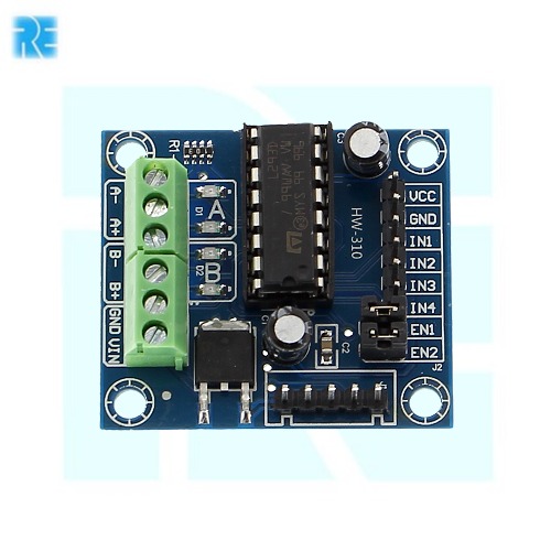 L293D 4 Channel DC Motor Driver E-4 Operating Voltage(VDC): 4.5 to 12 Peak Current (A): 600 Ma Motor Voltage supply: 9-12V
 -
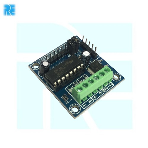
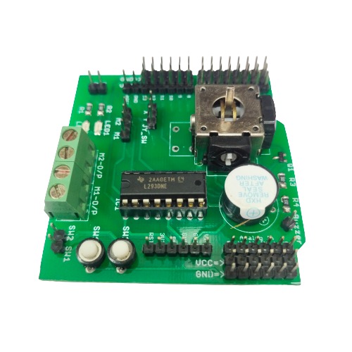
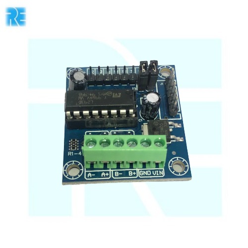 L293D Motor Driver Board E-40 L293D Motor Driver shield Input Voltage Range: 4.5 To 24VDC Output current Per Channel: 600mA Peak Output current: 1.2A

YOUR PARTNER IN TECHNOLOGY SOLUTIONS
YOUR PARTNER IN TECHNOLOGY SOLUTIONS


No.1030, Shriram Building,
Near Nagnath Par,
Sadashiv Peth, Pune – 411030,
Maharashtra, India
![]() Visit Our store
Visit Our store
STORE TIMINGS
Monday to Saturday
10:00 AM to 7.30 PM
(Store closed on all Sundays and Public Holidays)
NOTE
*All the prices are excluding Tax rates & are subject to change after a specific period of time.
Copyright © 2024@AbhinavDCS