-
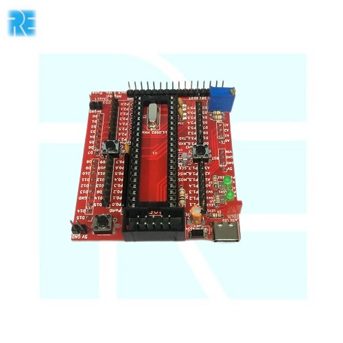
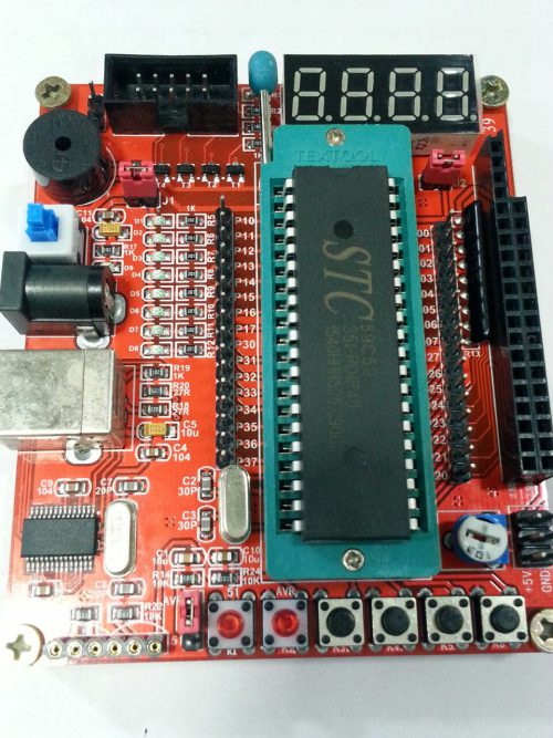
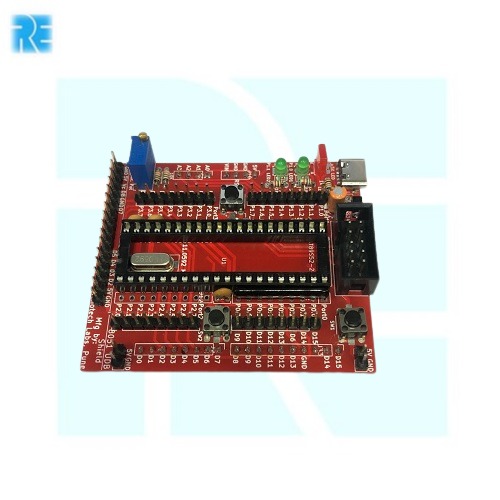 AT89S52 MCU (supports Other 8051 MCU Fits Supports 8051/AVR ISP Programmer for Programming Connector for 16 X 2 LCD Module. 2 Keys for Digital Inputs. 2 LED attached with Output Pin. USB C connector for powering board 5V Phone Charger
 -
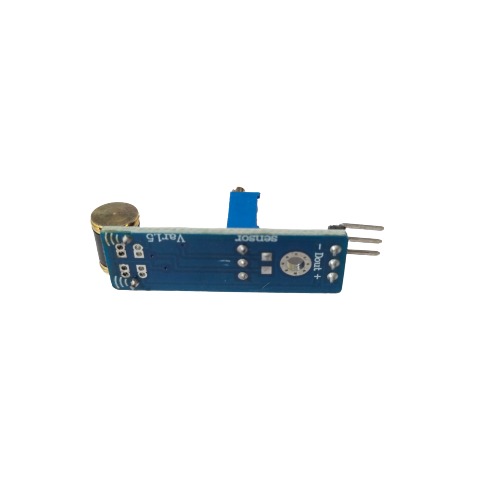
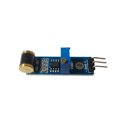
 Small size, low cost with patent's shock sensor 801S is a sensitivity shock sensor. Also have series shock sensor for industrial use.
 -
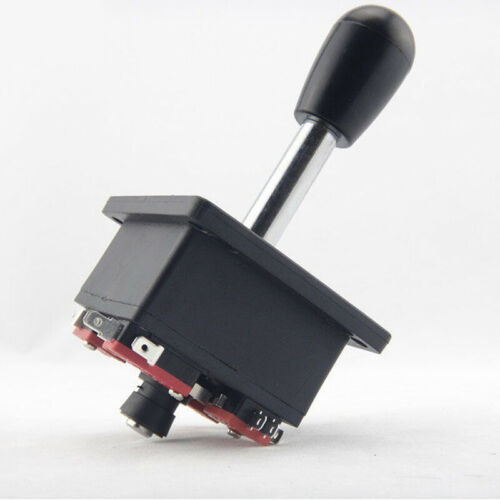
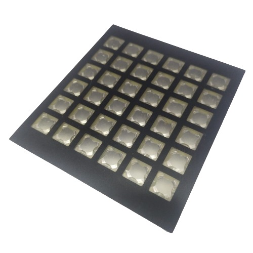
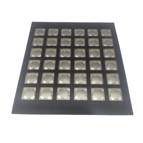
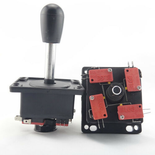 Non-replaceable top ball Suitable for game machine easy assemble after receive item. Change actuation to 4-way or 8-way simply by flipping actuator over
# Image shown is a representation only #
-
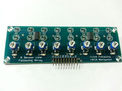 This is an infrared based sensor array which can be used in advanced line following and grid navigation robots. The array has 8 individual sensors placed next to each other. Each sensor has its own digital output and can sense the presence of a line and indicate it with a 5V logic output. On reading the the digital state of the eight sensors, the user can not only detect the line but also get to know how far the center of the robot is from the line. When all sensors sense the line, the robot is on an intersection. Features
- Uses 8 sensors for best resolution.
- Great useful in building fast line following and grid navigating robots.
- Input Voltage: 5V DC.
- Comes with easy to use digital outputs that can be connected directly to microcontrollers.
- The array has mounting holes of 3mm diameter for easy mounting.
-
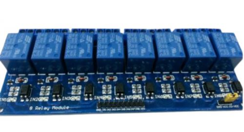 The 8 channel 12V relay module provides 8 optically isolated inputs that accept a wide range of voltage. This is a great way to switch on or off AC or DC loads using your Arduino. The relays are single-pole double-throw (SPDT) and are rated for 10A @ 250VAC. The ground for the relay coils is separate from the ground for the input signals. This, along with the optical isolation, provides a total galvanic isolation between the input and output. The two grounds could be joined together if desired with the included jumper. The relay coils run on 12VDC, and the module has screw-terminal blocks for sturdy and reusable attachments for the external load. The signal and power inputs run through the male single-row header.
 -
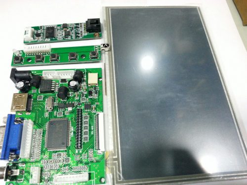 Overview:
- Small kit, easy to use .
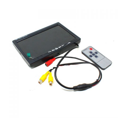
- The LCD driver board is HDMI/VGA/2AV Reversing Driver board.
- This controller board supports Automatically Switch to AV2(Reversing View camera). Please connected ACC to 12V. Power Supply is NOT included.
- If you want to conect this screen to your Raspberry Pi, you need a AV Cable or a HDMI Cable, or if you have a HDMI TO VGA CABLE for Raspberry pi, you can use a VGA Cable to connect your Raspberry pi to this Screen.
- There is a sticker on the LCD screen. Please peel off before use.
-
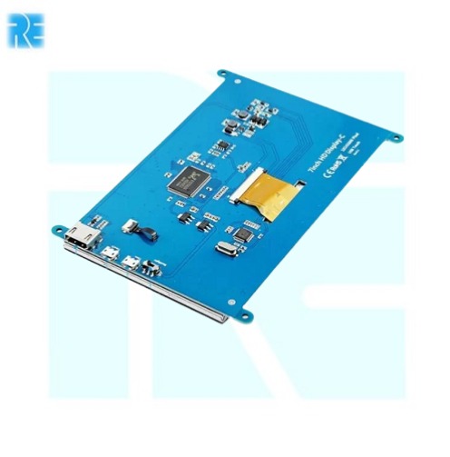
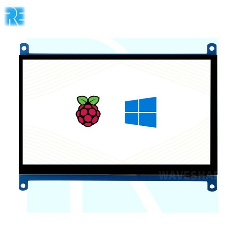 7 inch Capacitive Touch Screen LCD (C), 1024×600, HDMI, IPS, Low Power E-871 Brand: Waveshare Display Port: HDMI Display Panel: IPS Viewing Angle: 170 degree Touch Type: Capacitive Display Resolution: 1024×600. points capacitive touch control
 -
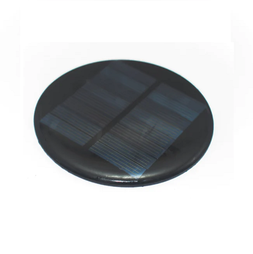
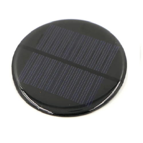 6V 80mA Mini Round Solar Panel 80mm E-857 Peak power: 4.8 Watt (Optional) Working current: 0-330mA(2W), 0-56mA(0.28W) Working voltage: 6V(2W), 5V(0.28W) Material: Polycrystalline Silicon
 -
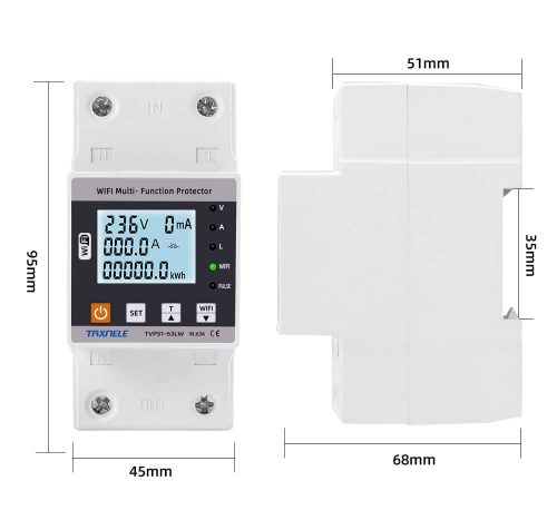
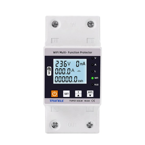 Measuring Range:-- AC 140-300V / Rated voltage-230V Operating Temperature:- -10C-65C Frequency:- 50Hz/60HZ Dimensions-45mm Din Rail
# Image shown is a representation only #
-
# Image shown is a representation only #
-
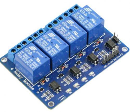
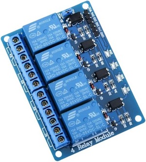 4-channel relay output modules, relay output contacts 250A 10A. Input IN1, IN2, IN3, IN4, the signal line LOW effective. VCC, GND power input, can relay a separate power supply relay power input of JD-VCC. Uses: support all MCU control. the industrial sector PLC control smart home control Wiring: VCC: positive power supply system GND: System power supply negative IN1 - IN4: relay control ports
 -
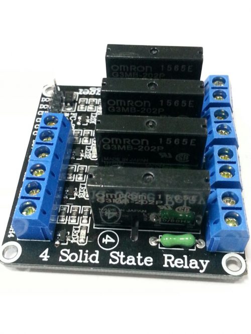 Specifications: -5V solid state relays 240V 2A, output with resistive fuse 240V 2A. -2.54cm pin and blue KF301 terminals to the control line is more convenient. -The input power supply: 5V DC (160MA) -The input control signal voltage: 0-2.5V low state relay OFF; -3.3-5V high state relay ON -Size: 57 x 55 x 20 mm(L x W x H)
 -
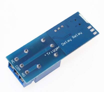
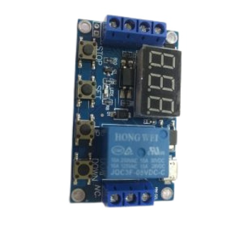
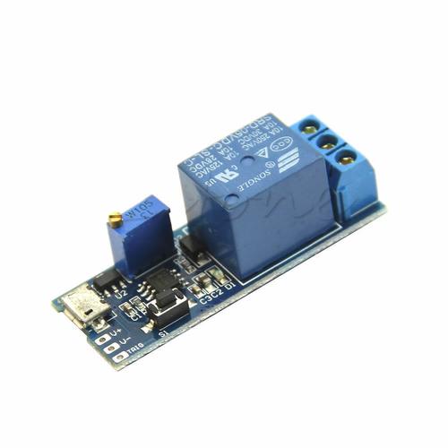 Highlights: By adjusting the potentiometer can set the length of time. MicroUSB 5.0V power supply with an input port, easy to use. 5 ~ 30V wide supply voltage. External signaltrigger and keytriggerin two ways. With a relay indicator. Anti-interference ability, the relay at various interference will not misoperation, suitable for industrial control.
 -

 5V USB Aluminium Body Power Bank Case for 18650 Battery-BLACK E-875 Input Power: 5V DC at up to 1.5A Output Power: 5V DC at up to 1A Stabilized Output Power Support replacement of 18650 Li-battery.
 -
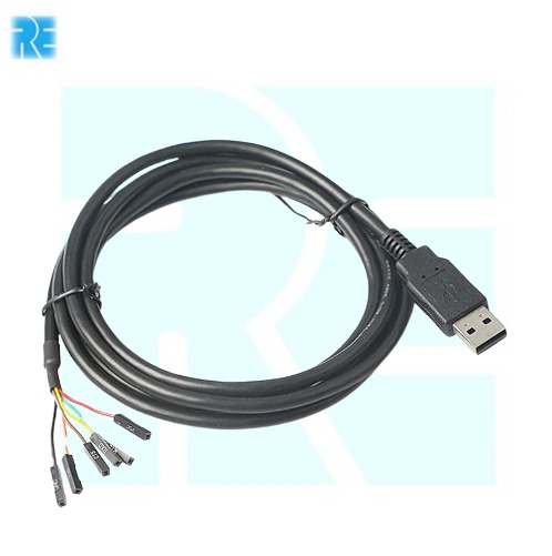
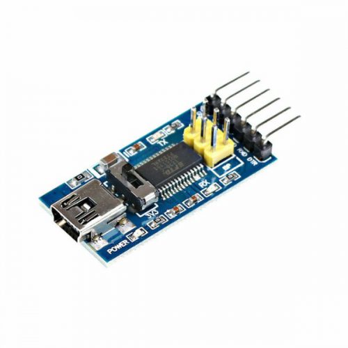 Feature: Chip: FT232RL Draw out all signal port of FT232RL chip RXD / TXD transceiver communication indicator USB power supply, can choose 5V or 3.3V, set by jumper With over current protection, using 500mA self-restore fuse Pin definition: DTR, RXD, TX, VCC, CTS, GND Pitch: 2.54mm Size: 36 x 18mm (L x W) Interface: Mini USB

YOUR PARTNER IN TECHNOLOGY SOLUTIONS
YOUR PARTNER IN TECHNOLOGY SOLUTIONS


No.1030, Shriram Building,
Near Nagnath Par,
Sadashiv Peth, Pune – 411030,
Maharashtra, India
![]() Visit Our store
Visit Our store
STORE TIMINGS
Monday to Saturday
10:00 AM to 7.30 PM
(Store closed on all Sundays and Public Holidays)
NOTE
*All the prices are excluding Tax rates & are subject to change after a specific period of time.
Copyright © 2024@AbhinavDCS