-
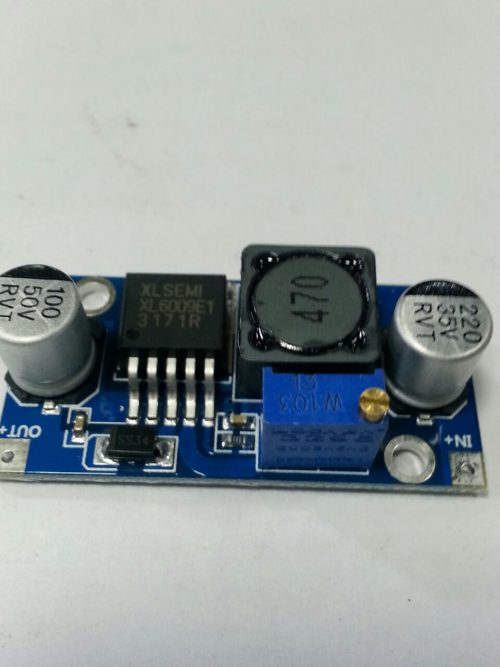 This DC-DC Module is based on IC XL6009E1 which is a high-performance step-up switching current (BOOST) module. The module uses the second generation of high-frequency switching technology XL6009E1 core chip that offers superior performance over the first generation technology LM2577. XL6009 replaces LM2577 module as LM2577 is about to be phased out.
 -
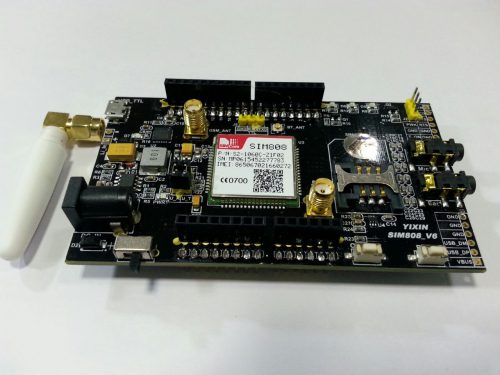 This SIM808 all in one Shield is a GSM and GPS Bluetooth all-in-one function module. It is based on the latest GSM/GPS module SIM808 from SIMCOM, supports GSM/GPRS Quad-Band network and combines GPS technology for satellite navigation. It features ultra-low power consumption in sleep mode and integrated with charging circuit for Li-Ion batteries, that make it get a super long standby time and convenient for projects that use rechargeable Li-Ion battery. It has high GPS receive sensitivity with 22 tracking and 66 acquisition receiver channels. Besides, it also supports A-GPS that available for indoor localization. The module is controlled by AT command via UART and supports 3.3V and 5V logical level. The hardware for SIM808 Shield is compatible with the Arduino.
 -
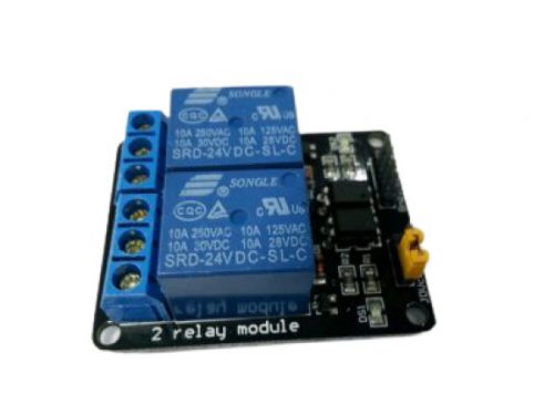 '-24V 2-Channel Relay interface board, and each one needs 50-60mA Driver Current. -Equipped with high-current relay, AC250V 10A ; DC30V 10A. -Standard interface that can be controlled directly by microcontroller (Arduino , 8051, AVR, PIC, DSP, ARM, ARM, MSP430, TTL logic). -Indication LED’s for Relay output status.
 -
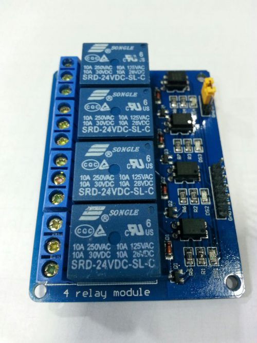 '-24V 4-Channel Relay interface board, and each one needs 50-60mA Driver Current. -Equipped with high-current relay, AC250V 10A ; DC30V 10A. -Standard interface that can be controlled directly by microcontroller (Arduino , 8051, AVR, PIC, DSP, ARM, ARM, MSP430, TTL logic). -Indication LED’s for Relay output status.
 -
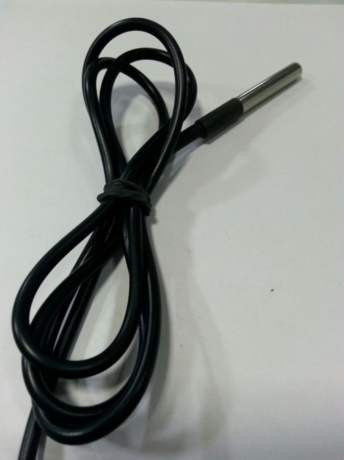 Cable specs: -Stainless steel tube 6mm diameter by 30mm long. -Cable is 36" long / 91cm, 4mm diameter. -Contains DS18B20 temperature sensor. -If your sensor has four wires - Red connects to 3-5V, Black connects to ground and White is data. The copper wire is soldered to the wire shielding. -If your sensor has three wires - Red connects to 3-5V, -Blue/Black connects to ground and Yellow/White is data. DS18B20 Technical specs: -Usable temperature range: -55 to 125°C (-67°F to 257°F). -9 to 12 bit selectable resolution. -Uses 1-Wire interface- requires only one digital pin for communication. -Unique 64 bit ID burned into chip. -Multiple sensors can share one pin. ±0.5°C Accuracy from -10°C to 85°C. -Temperature-limit alarm system. -Query time is less than 750ms. -Usable with 3.0V to 5.5V power/data.
 -
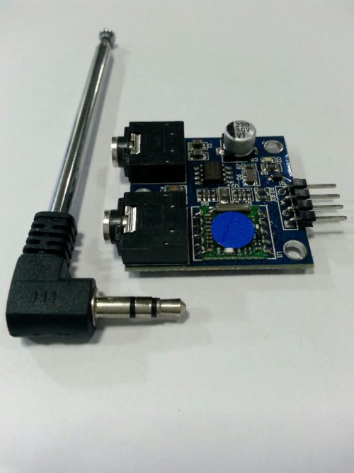 Feature: -Frequency range from 76-108MHZ automatic digital tuning. -High sensitivity, high stability, low noise, radio module. -A low-power electro-tuning FM stereo radio circuit, which integrates the IF frequency selection and demodulation network, can be completely free of tune. -High sensitivity (Using low noise RF input amplifier). -High-gain automatic gain control (AGC) circuit. -LC tuned oscillator fixed chip with low cost.
 -
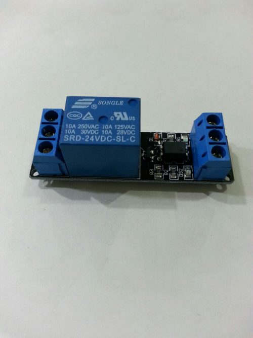 '-24V 1-Channel Relay interface board, and each one needs 50-60mA Driver Current. -Equipped with high-current relay, AC250V 10A ; DC30V 10A. -Standard interface that can be controlled directly by microcontroller (Arduino , 8051, AVR, PIC, DSP, ARM, ARM, MSP430, TTL logic). -Indication LED’s for Relay output status.
 -
 This shield V03 can achieve a simple two crunodal ZigBee network,achieve wireless communication between Arduino ,and allows the Arduino to wireless communicate over a modified ZigBee protocol using the popular XBee module.It works with all XBee modules including the Series 1 and Series 2.5, standard and Pro versions.
 -
 Description: The module is used in chip TM1638, a collection of these three common MCU peripheral circuit, the biggest feature is just take three microcontroller IO port to drive, do not need to scan display and key scanning microcontroller intervention, only need to read the relevant register send display data or test button, save MCU resources. We usually use an external microcontroller 8 LED, 8 digital tube, eight keys which will occupy the number of IO ports, far more than three IO mouth it, but with this module can be achieved. The practical application of key sensitive display good results. Wiring: VCC GND connected to 5V power supply, STB CLK DIO connected microcontroller IO port.
 -
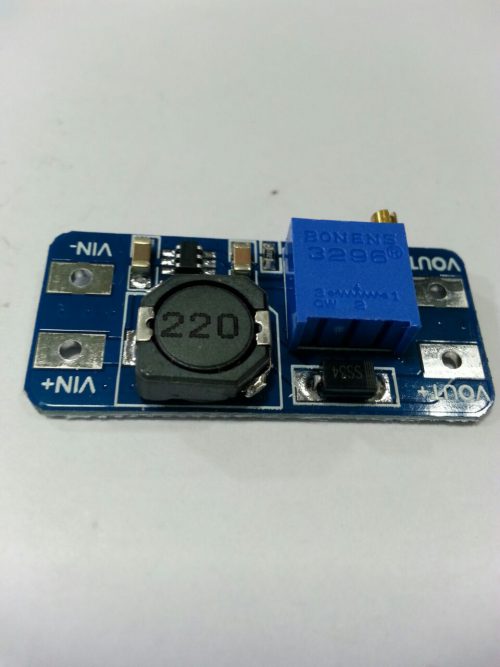 In = 2-24V / Out = 5-28V @ 2A Switching Regulator (Boost = Output Voltage has to be higher than input voltage), Good for getting stable 3.3V or 5V output from 1xAA or 2xAA or Li-ion batteries. Specifications: -2V to 24V input voltage with output boost 5V to 28V adjustable. -Maximum output current: 2A. -Input voltage: 2V ~ 24V. -Maximum output voltage: > 5V - 28V. -Efficiency: > 93%. -Input voltage should not exceed the maximum input voltage. -Peak current output current should not more than 2A. -Output voltage should always be higher than Input voltage. -PCB Size: 36 mm * 17 mm * 14 mm.
 -

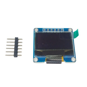 OLED Driver IC: SSD1306 Input Voltage: 3.3V ~ 6V Only Need 2 I/O Port to Control # Image shown is a representation only #
 -
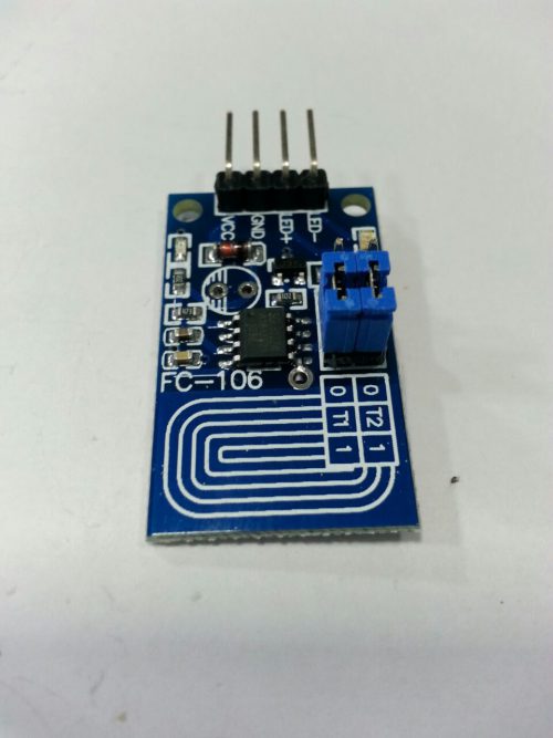 '-The lamp brightness can be adjusted by requirement,it is very to operate. -It can touch in medium protection,such glass,acrylic,plastic,ceramics and so on,which is very safe. -Wide application of voltage range,you can choose arbitrarily between 2.4V to 4.5V. -Anti power and phone interference,the EFT can reach above /-2KV;the touch response sensitivity and reliability will not affected by the close distance or multi-angle mobile phone interference. -Install: Needn’t to touch copper foil directly,the dimming can be processed across acrylic glass(above 3mm) or plastic. -Application:It can control LED module,light and so on.It is available for indoor LED,lighting lamp,DIY automotive lights dimming refit. -Function:Single touch,using the principle of capacitance touch .-The default function is switch,dimming,with brightness memories LED touch dimming.It will light slowly when turn on the lights,and become dark slowly when turn off,which effectively avoid the stimulation to eyes. -Dimming mode:Non-polar PWM dimming. -Wiring method:PCB board(VCC,GND) is power input,(LED , LED-) is connected with the LED lamps of positive and negative level (fingerprint) touch area, also can wire to lead out (the wiring should not be too long), copper skin area should be 2x3cm. With copper foil copper foil board module will side to the shell side.
 -
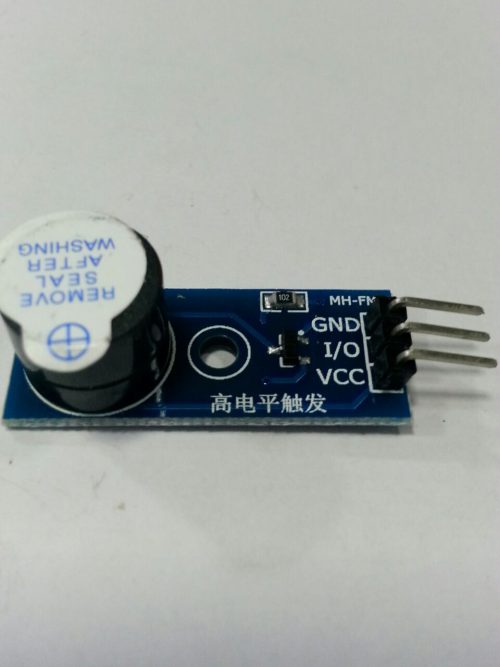 Bring oscillation source Audino 9012 drive Work Voltage:3.3V-5V Set bolt hole, easy to assemble PCB Dimension:3.3cm*1.3cm It and your Arduino will be able to play melodies. This is a small buzzer for the Sensor Shield. It creates different sound based on the different frequency of I/O toggling. Pin Definition : Vcc : 3.3V-5V GND : The Ground I/O : I/O Interface of SCM
 -
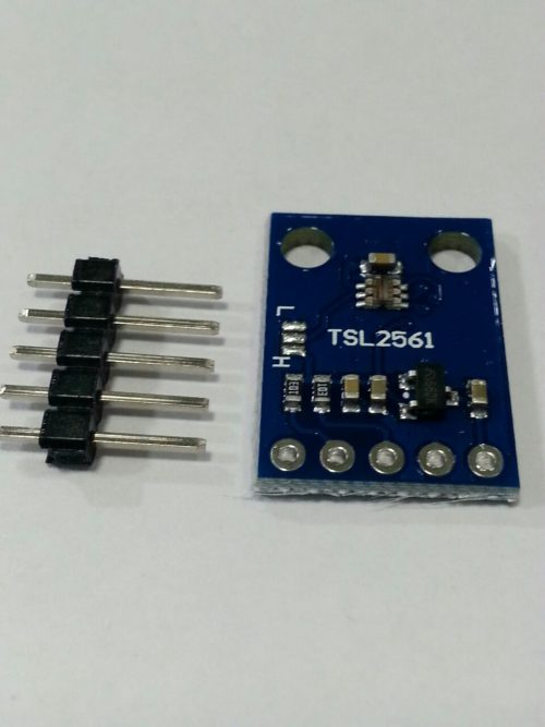 The TSL2561 is an inexpensive, yet sophisticated, light sensor. Unlike simpler sensors, like photoresistors and photodiodes, the TSL2561 incorporates both infrared and visible light sensors to better approximate the response of the human eye. Because the TSL2561 is an integrating sensor (it soaks up light for a predetermined amount of time), it is capable of measuring both very small and very large amounts of light.
 -
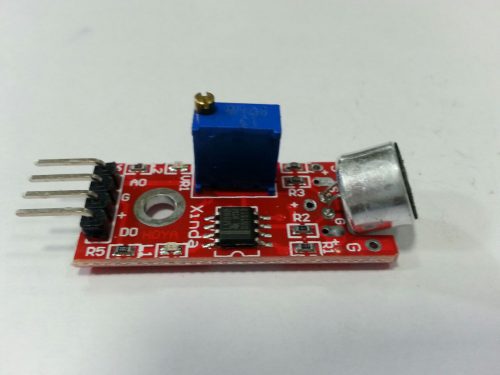 1, AO, analog output, real-time output voltage signal of the microphone 2, DO, when the sound intensity reaches a certain threshold, the output signal [high and low threshold - Sensitivity adjustment by potentiometer] Module features: 1, there is mounting screw holes of 3mm. 2, using the 5v DC power supply. 3, the analog output. 4, there is a threshold level output flip. 5, High sensitivity microphone, high sensitivity. 6, a power indicator light. 7, the comparator output indicator lamp.
 -
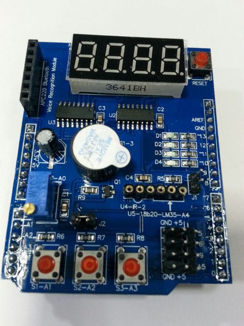 Multi function shield Features -4 digit 7-segment LED display module driven by two serial 74HC595’s. -4 LED’s. -10K potentiometer. -3 x push buttons. -Piezo buzzer. -DS18B20 temperature sensor interface (not included). -Infrared receiver interface. -Serial interface header for connection to serial modules.

YOUR PARTNER IN TECHNOLOGY SOLUTIONS
YOUR PARTNER IN TECHNOLOGY SOLUTIONS
No.1030, Shriram Building,
Near Nagnath Par,
Sadashiv Peth, Pune – 411030,
Maharashtra, India
![]() Visit Our store
Visit Our store
STORE TIMINGS
Monday to Saturday
10:00 AM to 7.30 PM
(Store closed on all Sundays and Public Holidays)
NOTE
*All the prices are excluding Tax rates & are subject to change after a specific period of time.
Copyright © 2024@AbhinavDCS