-
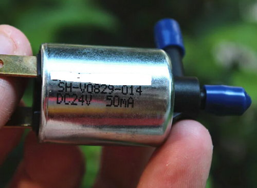
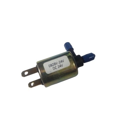 Use Fluid: AIR Air Leakage: 1c.c.max/min 220mmHg Pressure: MAX 7PSI
# Image shown is a representation only #
-
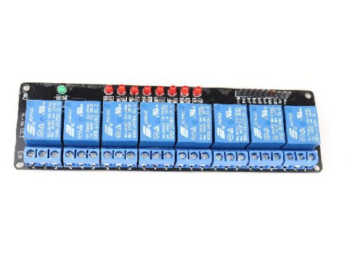
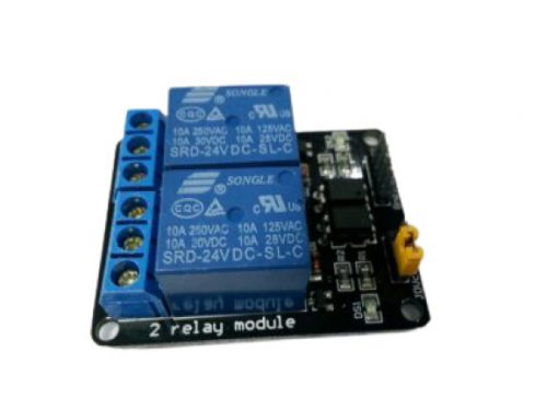 '-24V 2-Channel Relay interface board, and each one needs 50-60mA Driver Current. -Equipped with high-current relay, AC250V 10A ; DC30V 10A. -Standard interface that can be controlled directly by microcontroller (Arduino , 8051, AVR, PIC, DSP, ARM, ARM, MSP430, TTL logic). -Indication LED’s for Relay output status.
 -
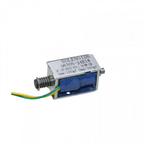
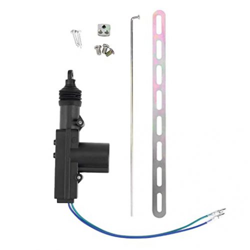 360 degree rotation Current consumption: 0.15A-2.22A Push & pull force:Â 4kg # Image shown is a representation only #
 -
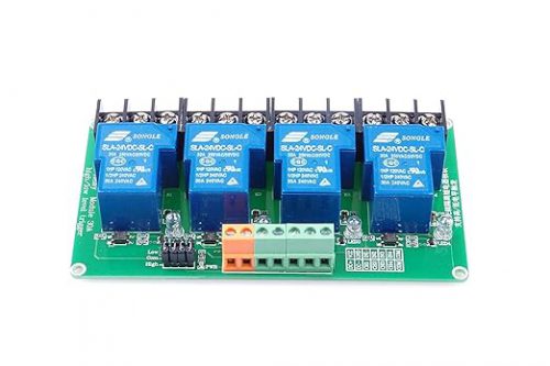
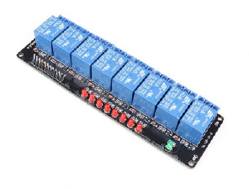
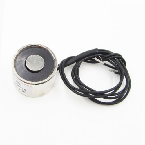
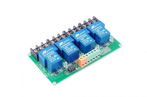 Supply Voltage - DC 24V / Quiescent Current: 5mA Maximum Operating Current - 190mA / Trigger Mode- high and low-level trigger Load Voltage- DC 30V / AC250 / Load Current- 30A
# Image shown is a representation only #
-
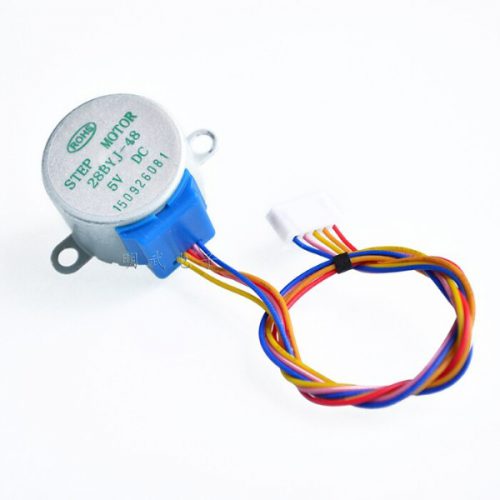
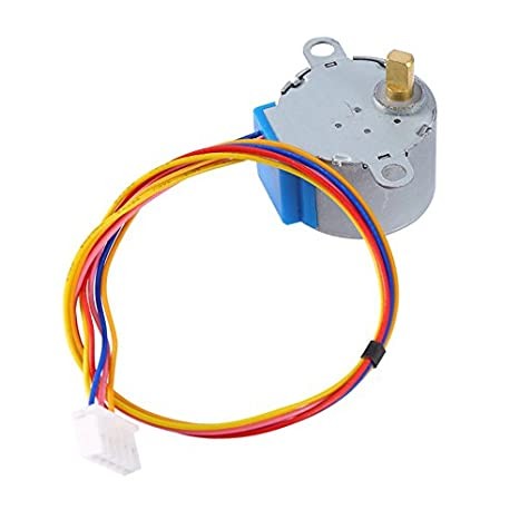 A unipolar stepper motor has one winding with center tap per phase. Each section of windings is switched on for each direction of magnetic field. Since in this arrangement a magnetic pole can be reversed without switching the direction of current, the commutation circuit can be made very simple (e.g., a single transistor) for each winding. Typically, given a phase, the center tap of each winding is made common: giving three leads per phase and six leads for a typical two phase motor. Often, these two phase commons are internally joined, so the motor has only five leads.
 -
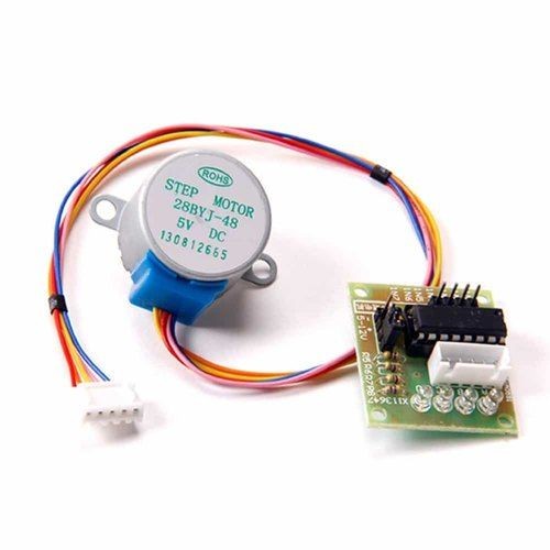 The 28-BYJ48 comes with Breakout using ULN2003 As a Motor driver chip . Rated voltage : 5VDC Number of Phase 4 Speed Variation Ratio 1/64 Stride Angle 5.625° /64 Frequency 100Hz DC resistance 50Ω±7%(25℃) Idle In-traction Frequency > 600Hz Idle Out-traction Frequency > 1000Hz In-traction Torque >34.3mN.m(120Hz) Self-positioning Torque >34.3mN.m Friction torque 600-1200 gf.cm Pull in torque 300 gf.cm Insulation grade A
 -
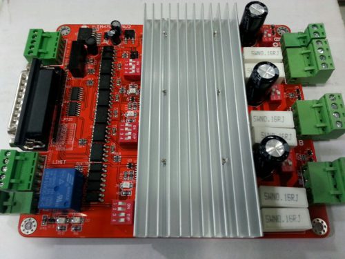 Product Features: 1. Toshiba TB6560AHQ chip - maximum 3.5 Adrive current, more powerful. 2. 1 - 1/16 microstep setting - higher accuracy, smoother operation. 3. Overload & over-current & over-temperature protection, full protection of your computer and peripheral equipment. 4. 4 files current settings can be set according to the user the actual current requirement. 5. Full closed-type optical isolation to protect the user's computer and equipment. 6. Professional design, two-stage signal processing, super anti-jamming. 7. Bipolar constant current chopper drive motor low-speed non-creeping phenomenon, noise, non-resonant region. 8. Four input control, you can set limit, emergency stop, which is divided into pairs of knives.
 -

 3 Speed Throttle for Ebike E-968 High-quality product Best Suitable for handle 22mm diameter Electric Bicycle Comes with a 3 Speed function Has a wide variety of applications VOLTAGE –5 V
 -
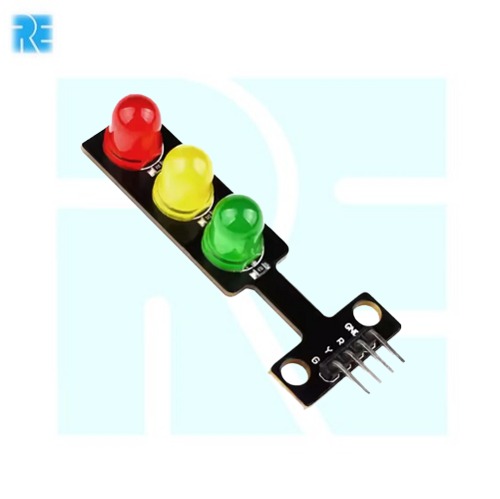 3-Color LED Traffic Signal Light Module E-941 Color : red, yellow, green LED Size: 10mm x 7. Brightness: Normal brightness. Voltage: 5V. Interface: common cathode red yellow green control.
 -
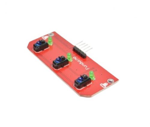 This Line Tracker sensor consists of 3 IR transmitter and IR receiver pairs. This tracker sensor is typically used for robots in line following task. It can be used for either dark or bright line following. The tracker sensor have 3 digital outputs to user indicating the existence of the line. Every sensor is provided with its own LEDs as indication of line detection.

YOUR PARTNER IN TECHNOLOGY SOLUTIONS
YOUR PARTNER IN TECHNOLOGY SOLUTIONS
No.1030, Shriram Building,
Near Nagnath Par,
Sadashiv Peth, Pune – 411030,
Maharashtra, India
![]() Visit Our store
Visit Our store
STORE TIMINGS
Monday to Saturday
10:00 AM to 7.30 PM
(Store closed on all Sundays and Public Holidays)
NOTE
*All the prices are excluding Tax rates & are subject to change after a specific period of time.
Copyright © 2024@AbhinavDCS