-
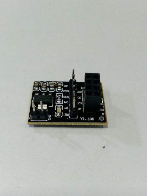 Specification: -Voltage: 3.3V. -It's for 8 Pin NRF24L01 Module. -A simple socket board which is for NRF24L01 wireless module. -On-board AMS1117-3.3 chip. -It can be used with NRF24L01 wireless module. -Dimension: 26 x 19 x 12mm.
 -
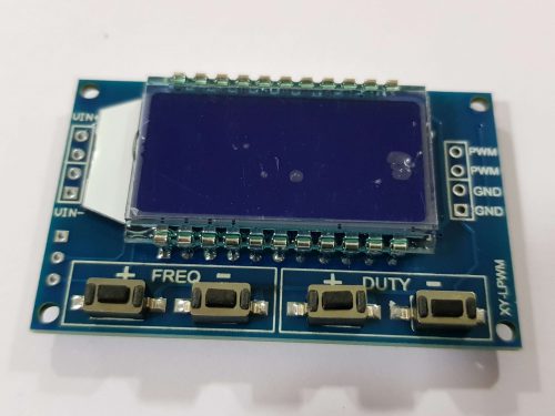 Description PWM output, you can set the frequency, duty cycle; Frequency is divided into four ranges, automatic switching: 1. XXX (no decimal point): the smallest unit is 1Hz, the value range of 1Hz ~ 999Hz; 2. X.XX (decimal point in the hundred) the smallest unit is 0.01Khz, the range of 1.00Khz ~ 9.99Khz; 3. XX.X (decimal point in ten): the smallest unit is 0.1Khz; value range of 10.0KHz ~ 99.9KHz 4. X.X.X (decimal point in ten and hundred): the smallest unit is 1Khz; value range 1KHz ~ 150KHz e.g. frequency display: 100 indicates PWM output 100Hz pulse; 1.01 indicates PWM output 1.01K pulse; 54.1 indicates that the PWM output has a pulse of 54.1 kHz; 1.2.4 indicates that the PWM output is 124 kHz pulse; Duty cycle range: 0 ~ 100%;
 -
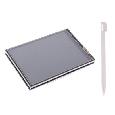
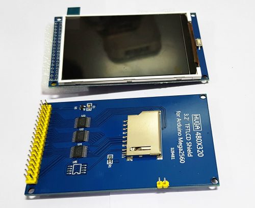
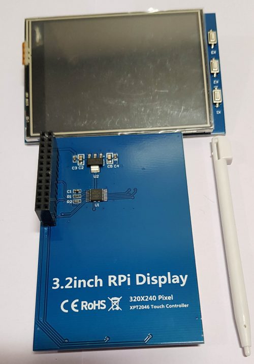
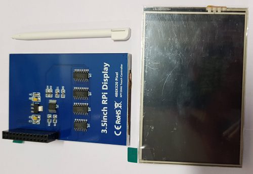
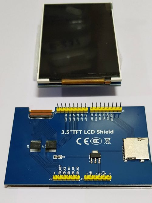 Resistive touch screen TFT LCD, 3.5inch, 480x320 resolution 4-wire resistive touchscreen 8-bit digital interface, plus 4 control lines
 -
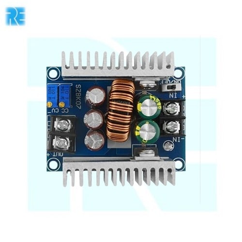
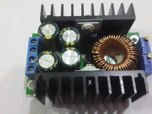
 300W 20A DC-DC Buck Converter Step-down Module Constant Current LED Driver Module E-954 High-power LED driver. Lithium battery(or lead accumulator) charge. Vehicle-mounted power supply. Low voltage system power supply. 6V, 12V, 14V, 24V battery charge. On-board laptop power supply. regulated power supply. Low voltage power supply system.
 -
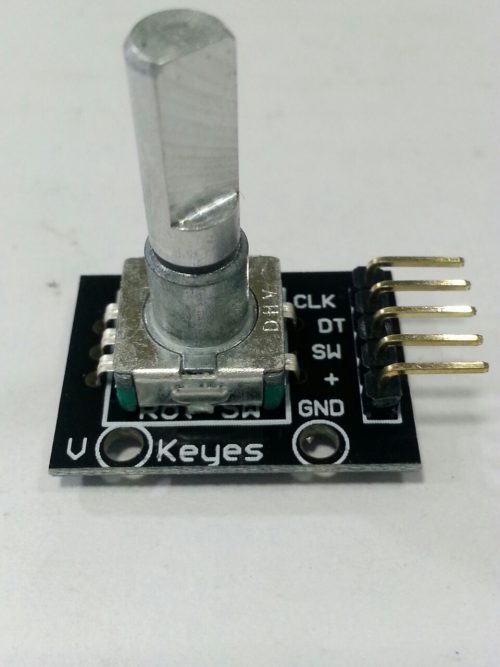 The rotary encoder is a rotary input device (as in knob) that provides an indication of how much the knob has been rotated AND what direction it is rotating in. It’s a great device for stepper and servo motor control. You could also use it to control devices like digital potentiometers. A rotary encoder has a fixed number of positions per revolution. These positions are easily felt as small “clicks” you turn the encoder.
 -
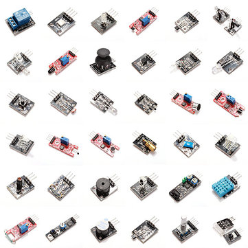 The kit contains:
- JoyStick
- Flame Sensor
- RGB LED
- Heartbeat Sensor
- Light Cup
- Hall Magnetic Sensor
- Relay
- Linear Hall Sensor
- SMD RGB
- 7 Color Flash
- Tilt Switch
- Temperature Sensor
- Big Sound Sensor
- Touch Sensor
- Two-Color LED
- Laser Emitter
- Ball Switch
- Analog Temperature Sensor
- Small Sound Sensor
- Digital Temperature Sensor
- Two-Color LED (small)
- Button
- Photoresistor
- IR Emission
- Tracking Sensor
- Buzzer
- Reed Switch
- Shock Sensor
- Temperature And Humidity Sensor
- IR Receiver
- Avoidance Sensor
- Passive Buzzer
- Mini Reed
- Rotary Encoders
- Analog Hall Sensor
- Tap Module
- Light Blocking
-
 38PIN ESP32 Expansion Board With TYPE-C/Micro USB E-882 Interface type: Standard 38Pin interface USB interface: 1 TYPE-C interface: 1 DC interface: 1

YOUR PARTNER IN TECHNOLOGY SOLUTIONS
YOUR PARTNER IN TECHNOLOGY SOLUTIONS
No.1030, Shriram Building,
Near Nagnath Par,
Sadashiv Peth, Pune – 411030,
Maharashtra, India
![]() Visit Our store
Visit Our store
STORE TIMINGS
Monday to Saturday
10:00 AM to 7.30 PM
(Store closed on all Sundays and Public Holidays)
NOTE
*All the prices are excluding Tax rates & are subject to change after a specific period of time.
Copyright © 2024@AbhinavDCS