-
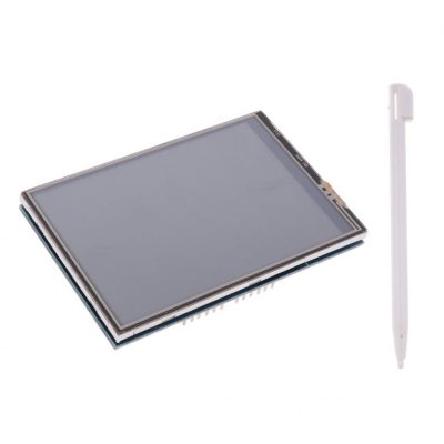
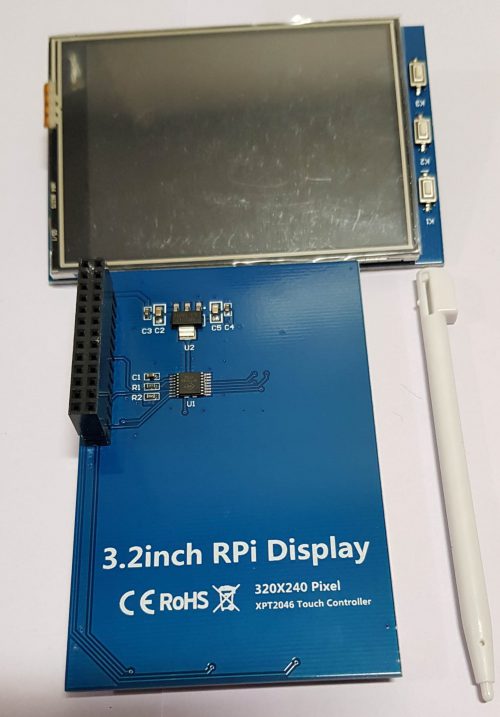
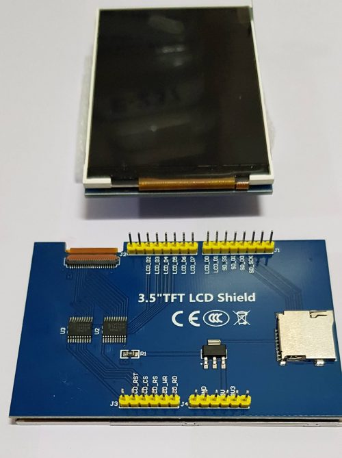 Resistive touch screen TFT LCD, 3.5inch, 480x320 resolution 4-wire resistive touchscreen 8-bit digital interface, plus 4 control lines
 -
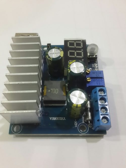 This constant Voltage current boost module has high efficiency and little heat, low ripple and Stable performance With digital display, can show input Voltage), output Voltage) and output current) Output with USB interface and identification resistor, a single Lithium battery can be boosted to 5V to charge your phone Has over current protection and short circuit protection(input 15A fuse), safe to use Application: DIY a stabilized power supply, charge your electronic devices, stabilize Voltage for solar panel and etc
 -
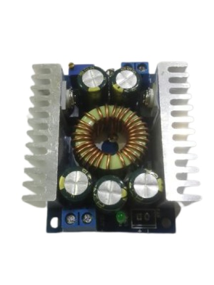 Input voltage: 5-40V;Output voltage: 1.2-30V adjustable,1.2-30V fixed output Output Current: 12A MAX (rated 8A, peak 12A) 100W enhance heat dissipation of up to 200W,Working temperature: -40 to 85 degrees Operating frequency: 180KHz;Conversion efficiency: up to 95% Short circuit protection: Yes (limit current 12A) Overtemperature protection: (automatically shut off the output after overtemperature) Input Reverse Polarity Protection: None Installation: four 3mm screws (not included) Connection: terminals, solderless, V-IN is the input, V-OUT is the output, with wire output module housing. Module size: 50mm * 50mm * 18mm Application: This module can be used in batteries, power transformers, DIY adjustable power supply, 24V car T of the power supply, automotive LED lights with power, industrial Buck equipment, 12V t- 3.3V, 12V - 5V, 24V - 5V , 24V -12V, etc. Package Included:1 x Buck Converter Module Note:Light shooting and different displays may cause the color of the item in the picture a little different from the real thing. The measurement allowed error is /- 1-3 cm.
 -
 1. STM32F103RCT6: the high performance STM32 MCU in LQFP64 package which features * Core: ARM Cortex-M3 32-bit RISC; * Operating Frequency: 72MHz, 1.25 DMIPS/MHz; * I/Os: 51; * Operating Voltage: 2-3.6V; * Memories: 256kB Flash, 48kB RAM; * Communication Interfaces: 2 x SPI, 5 x USART, 2 x I2S, 2 x I2C, 1 x SDIO, 1 x USB, 1 x CAN; * AD & DA converters: 3 x AD(12-bit, 1s, shares 16 channels); 2 x DA(12-bit); * Debugging/Programming: supports JTAG/SWD (serial wire debug) interfaces, supports IAP; 2. AMS1117-3.3V: 3.3V voltage regulator; 3. Power supply switch: 5V DC or USB; 4. Power indicator; 5. LEDs: Convenient for indicating I/O status or program debugging running state; 6. Reset button; 7. User key; 8. Joystick: Convenient for I/O input (five positions); 9. 32.768K crystal oscillator: used for internal RTC, also supports clock calibration; 10. 8M crystal oscillator: enables the MCU run at 72M frequency by frequency multiplication; 11. SDIO Interface: connects to the Micro SD adapter easily, It is much faster to read/write the Micro SD card via SDIO than via SPI; 12. 8-Bit I/O Interface: easily connects to keypad, motor, etc; 13. CAN Interface: communicates with accessory boards which feature the CAN device conveniently; 14. SPI1 / SPI2 interface: * Easily connects to SPI peripherals such as FLASH (AT45DBxx), SD card, MP3, etc.; * Convenient for connecting AD, DA module, thanks to the SPI1 alternative function - AD&DA; 15. I2C1 / I2C2 interface: easily connects to I2C peripherals such as I/O expander (PCF8574), EEPROM (AT24Cxx), etc.; 16. LCD Interface: easily connects to the touch screen LCD; 17. ONE-WIRE Interface: easily connects to ONE-WIRE devices (TO-92 package), such as temperature sensor (DS18B20), electronic registration number (DS2401), etc. 18. PS/2 Interface: easily connects to PS/2 keyboard or mouse; 19. USART1 Interface: easily connects to RS232, RS485, USB TO 232; 20. USART2 Interface: easily connects to RS232, RS485, USB TO 232; 21. USB Port: USB communication between board and PC; 22. 5V DC jack; 23. 5V/3.3 V power input/output: usually used for power output, or common ground with other user board; 24. MCU pins connector: all the MCU pins are accessible on expansion connectors for further expansion; 25. JTAG/SWD interface: for debugging/programming; 26. Boot Mode Selection: for configuring the BOOT0 and BOOT1 pins.
 -
 Features Raspberry Pi Night Vision Camera, supports all revisions of the Pi 5 megapixel OV5647 sensor Camera specifications CCD size : 1/4inch Aperture (F) : 1.8 Focal Length : 3.6MM (adjustable) Diagonal : 75.7 degree Sensor best resolution : 1080p 4 screw holes Used for attachment Provides 3.3V power output Supports connecting infrared LED and/or fill flash LED Dimension : 25mm x 24mm
 -
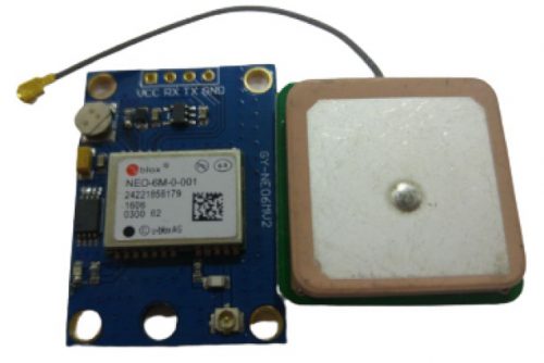 '-U-BLOX NEO-6M module with high-gain active antenna; -TTL level, compatible with 3V/5V systems; -Baud rate: 9600kbps (default), adjustable by u-center; -Provided IPX interface for different active antennas; -Provided rechargeable battery backup, enabling to save ephemeris data on power down; -Support hot start.
 -
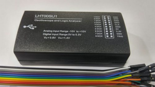
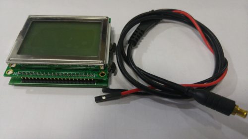 '- 2.0" LCD display - Resolution: 128 x 64 - Core processor: AVR - Core size: 8-bit - Sample rate: 250k - Trigger level: 0~5.1V - Dual channel (no coupling) - Comes with USB cable (76cm) and probe cable (25cm)
 -
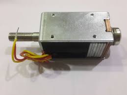
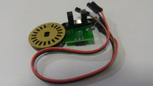 Working voltage: 4.5V to 5.5 V. Transmit tube pressure drop: Vf = 1.6 V Transmit tube current: 20 mA Signal output: A, B two way; The TTL level Distinguish precision: 0.01 mm Measurement frequency, 100 KHZ Encoder diameter: 24 mm Encoder type D hole diameter: 4 mm The encoder resolution: 20 line Speed measuring sensor configuration: The configuration can measures 1 road motor speed
 -
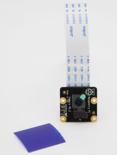 The Pi NoIR gives you everything the regular Camera Module offers, with one difference: it does not employ an infrared filter. (NoIR = No Infrared.) This means that pictures you take by daylight will look decidedly curious, but it gives you the ability to see in the dark with infrared lighting. We bundle a little square of blue gel with the Pi NoIR, which you can use with the camera to monitor the health of green plants. The Pi NoIR is very popular among wildlife hobbyists: with a few infrared LEDs, you can monitor what nocturnal animals are doing in your garden without disturbing them. The camera works with all models of Raspberry Pi 1, 2, and 3. It can be accessed through the MMAL and V4L APIs, and there are numerous third-party libraries built for it, including the Picamera Python library. See the Getting Started with Picamera resource to learn how to use it.
 -
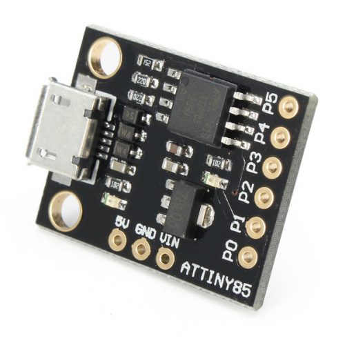 Features: >The smallest Arduino Compatible breakout board measuring less than 1 square inch! >Support for the Arduino IDE 1.0 (OSX/Win/Linux). >Power via USB or External Source: 7V - 35V DC (12v or less recommended). >Automatic selection between 5V USB and External Source for Power. >On-board 500ma 5V Regulator. >On-board microUSB port for easy programming & power. >6 I/O Pins: 2 pins (P3 & P4) are tied to USB (This means if your program actively communicates over USB they will be in use. If your program does not actively communicate over USB you can use all 6 I/O pins after programming via USB). >8k Flash Memory (about 6k after bootloader). >Communication Protocols Supported: I2C and SPI T. >PWM on 3 pins (more possible with Software PWM). >ADC on 4 pins. >Power LED and Status LED on-board.
 -
 1. Low RDS (On) Output 2. Automatic current decay mode detection / selection 3. Mix with slow current decay modes 4. Synchronous rectification for low power dissipation 5. Internal UVLO 6. Cross-current protection 7. 3.3 and 5 V compatible logic supply 8. Thermal shutdown circuitry 9. Ground fault protection. 10. Load short-circuit protection 11. Optional step five modes: full, 1/2, 1/4, 1/8 and 1/16
 -
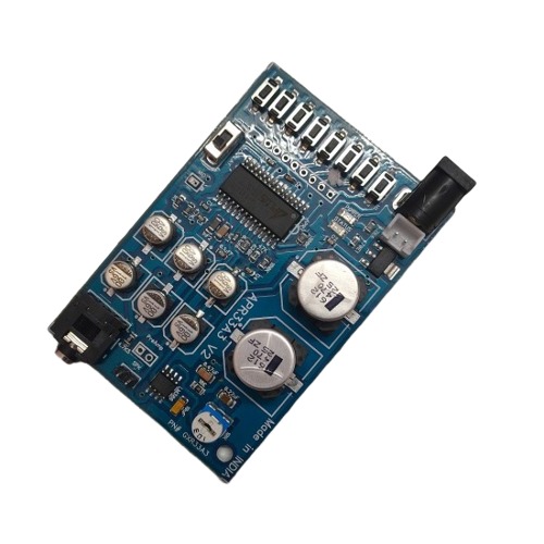 *FEATURES *Operating Voltage Range: 3V ~ 6.5V *Single Chip, High Quality Audio/Voice Recording & Playback Solution. *No External ICs Required. *Minimum External Components. *User Friendly, Easy to Use Operation. *Programming & Development Systems Not Required. *170/ 340/ 680 sec. Voice Recording Length in aPR33A1/aPR33A2/aPR33A3 *Powerful 16-Bits Digital Audio Processor. *Nonvolatile Flash Memory Technology *No Battery Backup Required. *External Reset pin. *Powerful Power Management Unit *Very Low Standby Current: 1uA *Low Power-Down Current: 15uA *Supports Power-Down Mode for Power Saving.
 -
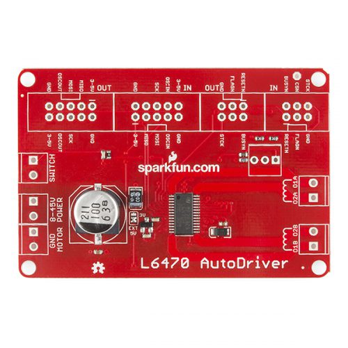 L6470 is a 3A, 8-45V bipolar stepper motor driver. It has built-in overcurrent detection, undervoltage detection, overtemperature detection, stall detection, a 5-bit ADC, and a switch input that can be used for either user jog control or as a hard stop function. As if that weren’t enough, it also features microstepping support (up to 128 microsteps per full step) and PWM drive voltage limiting. The logic supply voltage supports both 3.3V and 5V I/O levels.
 -
# Image shown is a representation only #
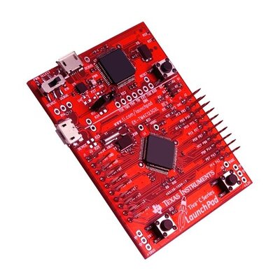
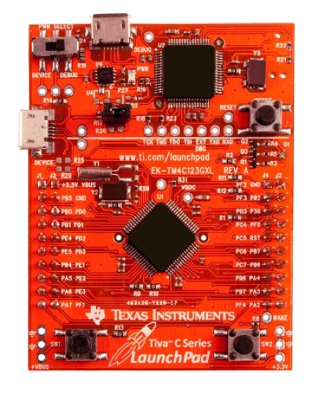
80MHz 32-bit ARM Cortex-M4-based microcontrollers CPU High Performance TM4C123GH6PM MCU Dual 12-bit 2MSPS ADCs, motion control PWMs -
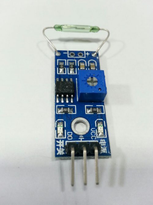 Dry reed pipe needs and magnet is used together, in the induction to have certain magnetic, a conducting state, module output low level, no magnetic, is off state, output high level, dry reed pipe and magnetic induction distance within in 1.5 cm beyond insensitive or will not trigger phenomenon. Module DO output end of the single chip microcomputer can I/O port directly connected, through the single chip microcomputer can detect dry reed pipe state trigger. Module DO output end and relay IN end connected to form high power dry reed pipe switch, direct control high voltage.
 -
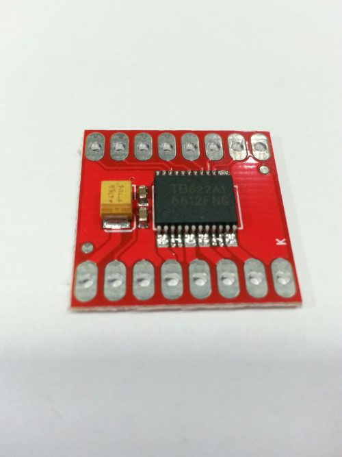 The TB6612FNG motor driver can control up to two DC motors at a constant current of 1.2A (3.2A peak). Two input signals (IN1 and IN2) can be used to control the motor in one of four function modes - CW, CCW, short-brake, and stop. Features:
- Power supply voltage: VM=15V max, VCC=2.7-5.5V
- Output current: Iout=1.2A(average) / 3.2A (peak)
- Standby control to save power
- CW/CCW/short brake/stop motor control modes
- Built-in thermal shutdown circuit and low voltage detecting circuit
- All pins of the TB6612FNG broken out to 0.1" spaced pins
- Filtering capacitors on both supply lines

YOUR PARTNER IN TECHNOLOGY SOLUTIONS
YOUR PARTNER IN TECHNOLOGY SOLUTIONS


No.1030, Shriram Building,
Near Nagnath Par,
Sadashiv Peth, Pune – 411030,
Maharashtra, India
![]() Visit Our store
Visit Our store
STORE TIMINGS
Monday to Saturday
10:00 AM to 7.30 PM
(Store closed on all Sundays and Public Holidays)
NOTE
*All the prices are excluding Tax rates & are subject to change after a specific period of time.
Copyright © 2024@AbhinavDCS