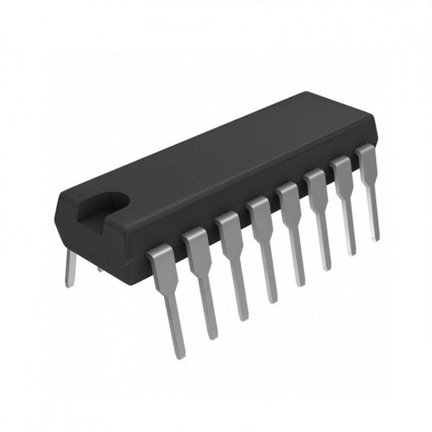
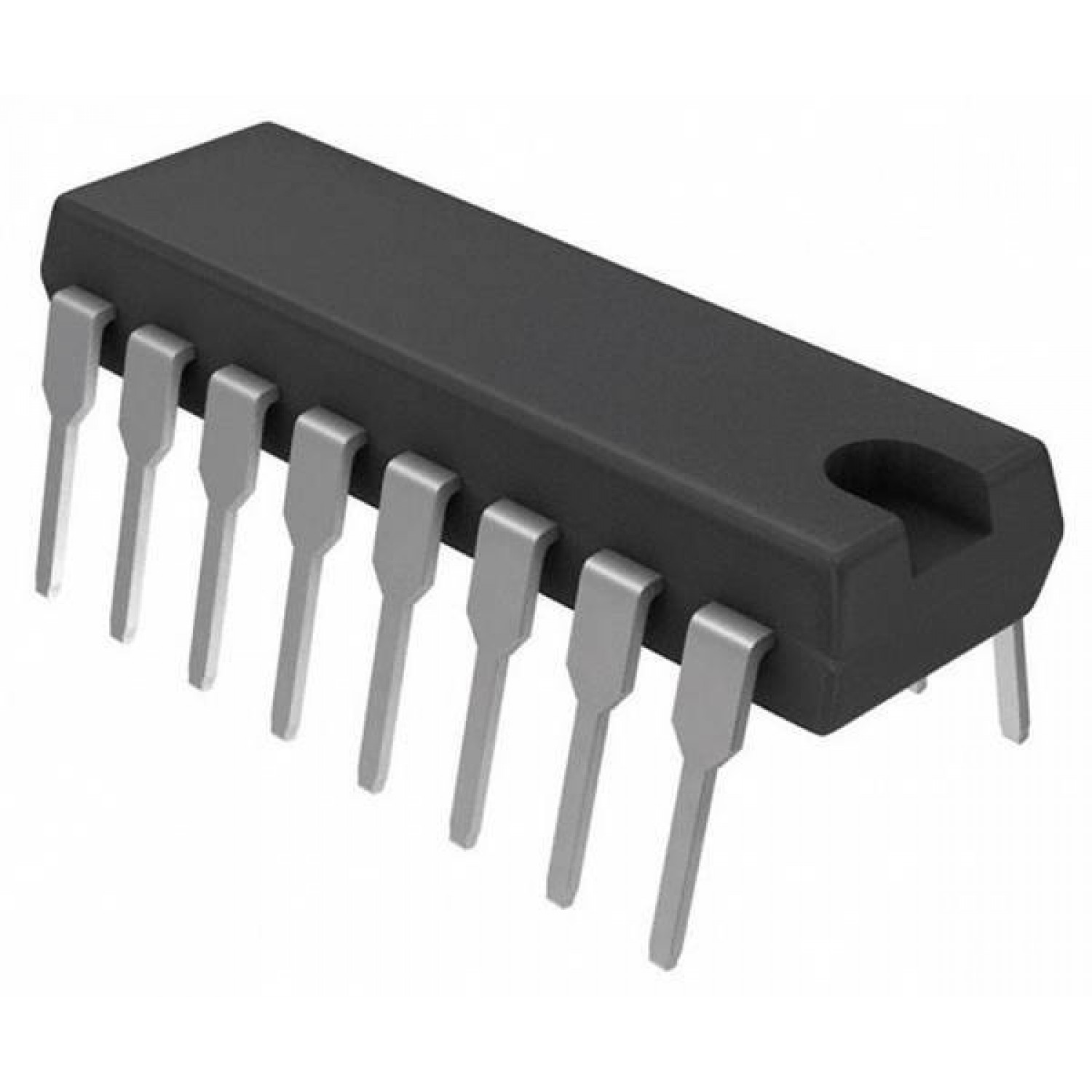
LM13600N Dual Operational Transconductance Amplifier (OTA) DIP-16 (LM13600N DIP IC)
The LM13600N is a high-performance monolithic integrated circuit consisting of two independent operational transconductance amplifiers (OTA). Each amplifier features differential inputs and a push-pull output. A unique aspect of the LM13600N is the inclusion of internal linearizing diodes at the inputs, which significantly reduces distortion and allows for higher input signal levels. Additionally, each OTA is equipped with an independent Darlington emitter follower buffer to provide low-impedance output drive capability.
This IC is primarily used in voltage-controlled amplifiers (VCA), voltage-controlled filters (VCF), and voltage-controlled oscillators (VCO). It is a highly specialized and legendary component for Arduino electronics projects in India involving analog music synthesis, DIY modular synthesizers, automated gain control (AGC) circuits, and voltage-tunable active filters.
Key Features
- Dual independent OTAs in a single 16-pin package
- Internal linearizing diodes for reduced harmonic distortion
- Integrated output Darlington buffers for low-impedance drive
- Transconductance is directly proportional to the amplifier bias current (Iabc)
- Wide supply voltage range (up to +/- 18V)
- Excellent matching between the two amplifiers
- High input impedance and high output impedance (before buffer)
- Wide transconductance range (over 6 decades)
Specifications
- IC Type = Dual Operational Transconductance Amplifier (OTA)
- Supply Voltage = +/- 2V to +/- 18V (Dual) or 4V to 36V (Single)
- Transconductance (gm) = 9600 umho (Typical at 500uA Iabc)
- Peak Output Current = 650uA (Typical)
- Buffer Slew Rate = 2V/us
- Package Type = DIP
- Number of Pins = 16
- Mounting Type = Through-Hole
- Operating Temperature = 0 to 70 degrees Celsius
Interfaces
- AMP BIAS (Iabc) = Current Input to Control Transconductance
- DIODE BIAS = Current Input for Linearizing Diodes
- +INPUT, -INPUT = Differential Signal Inputs
- OTA OUTPUT = High-Impedance Current Output
- BUFFER IN = Input to Darlington Emitter Follower
- BUFFER OUT = Low-Impedance Voltage Output
- V+ = Positive Supply Voltage
- V- = Negative Supply Voltage