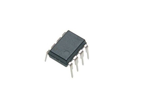
LT1013DN-8 Dual Precision Operational Amplifier DIP-8 (LT1013DN8 IC)
The LT1013DN-8 is a high-performance dual precision operational amplifier manufactured by Analog Devices. It is the first dual op-amp designed in the industry-standard 8-pin DIP configuration to provide precision specifications while operating from a single 5V supply. This makes it a significant upgrade for legacy designs using the MC1458, LM158, or OP-221, as it eliminates the crossover distortion typically found in older single-supply op-amps.
In the Indian market, this IC is frequently utilized in battery-powered instrumentation, 4mA-to-20mA current loop transmitters, and active filters. Its ability to have both input and output ranges include ground while operating on a single supply makes it ideal for precision signal conditioning in modern low-voltage systems.
Key Features
- Single-Supply Operation: Fully specified for single 5V and dual ±15V power supplies.
- Ground-Sensing Inputs: The common-mode input voltage range extends directly to the negative rail (ground).
- True Zero Output: The output can swing to within a few millivolts of ground while sinking current.
- High Precision: Features a low maximum input offset voltage of 150μV and low drift of 2μV/°C.
- Low Power: Guaranteed low supply current of only 500μA maximum per amplifier.
- High Drive Capability: The new output stage design can source and sink in excess of 20mA of load current.
- Quiet Performance: Low voltage noise (0.55μVp-p) and low current noise, outperforming the industry-standard OP-07.
Specifications
- IC Type: Dual Precision Operational Amplifier
- Number of Channels: 2
- Gain Bandwidth Product: 1 MHz
- Slew Rate: 0.4 V/μs
- Input Offset Voltage: 60 μV (Typical) / 200 μV (Max)
- Input Bias Current: 15 nA (Typical)
- Supply Voltage Range: 4V to 44V (Single) or ±2V to ±22V (Dual)
- Voltage Gain: 120 dB (Typical)
- Package Type: PDIP-8 (Through-Hole)
- Operating Temperature: 0°C to 70°C
Pinout Configuration (8-Pin DIP)
- Pin 1 (OUTPUT A): Output of the first amplifier.
- Pin 2 (–IN A): Inverting input of the first amplifier.
- Pin 3 (+IN A): Non-inverting input of the first amplifier.
- Pin 4 (V–): Negative supply voltage or Ground.
- Pin 5 (+IN B): Non-inverting input of the second amplifier.
- Pin 6 (–IN B): Inverting input of the second amplifier.
- Pin 7 (OUTPUT B): Output of the second amplifier.
- Pin 8 (V+): Positive supply voltage.