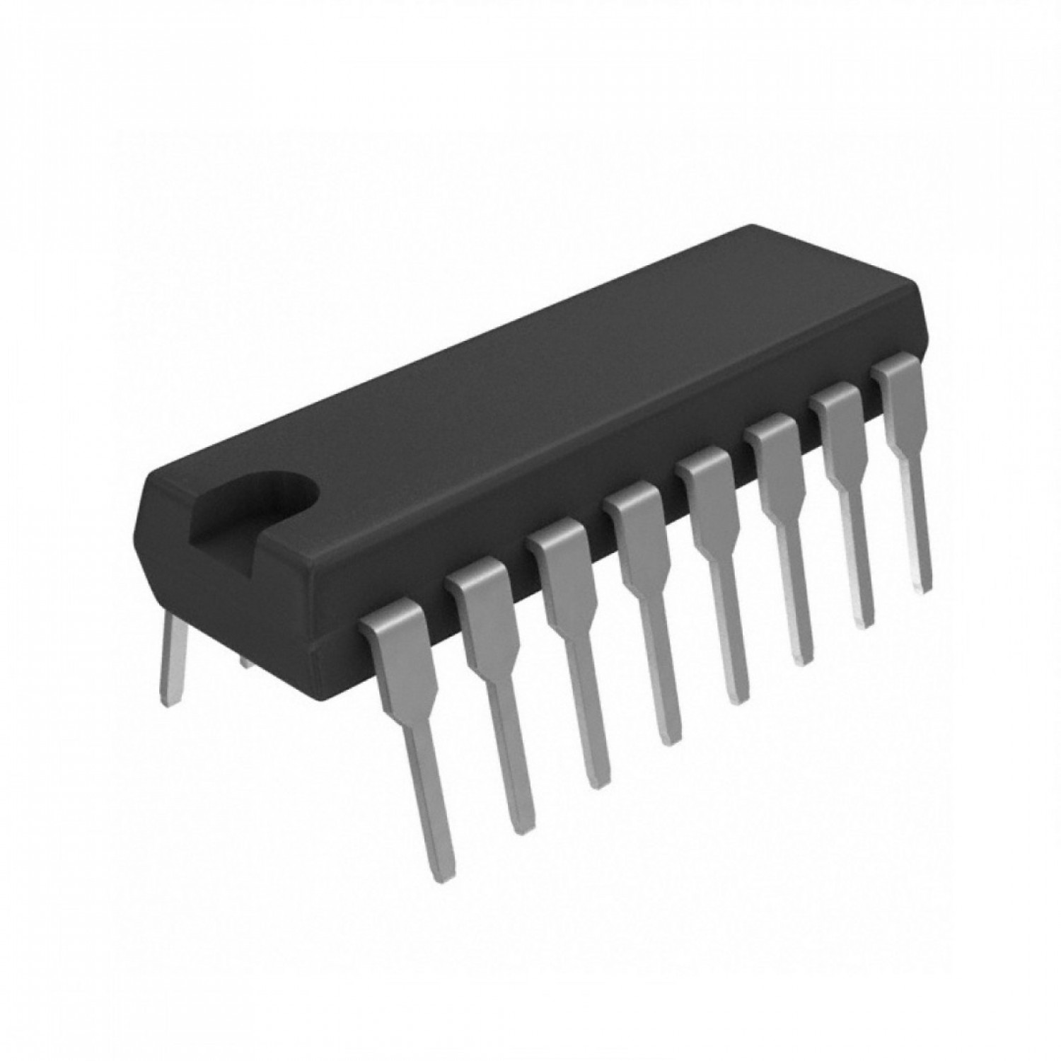
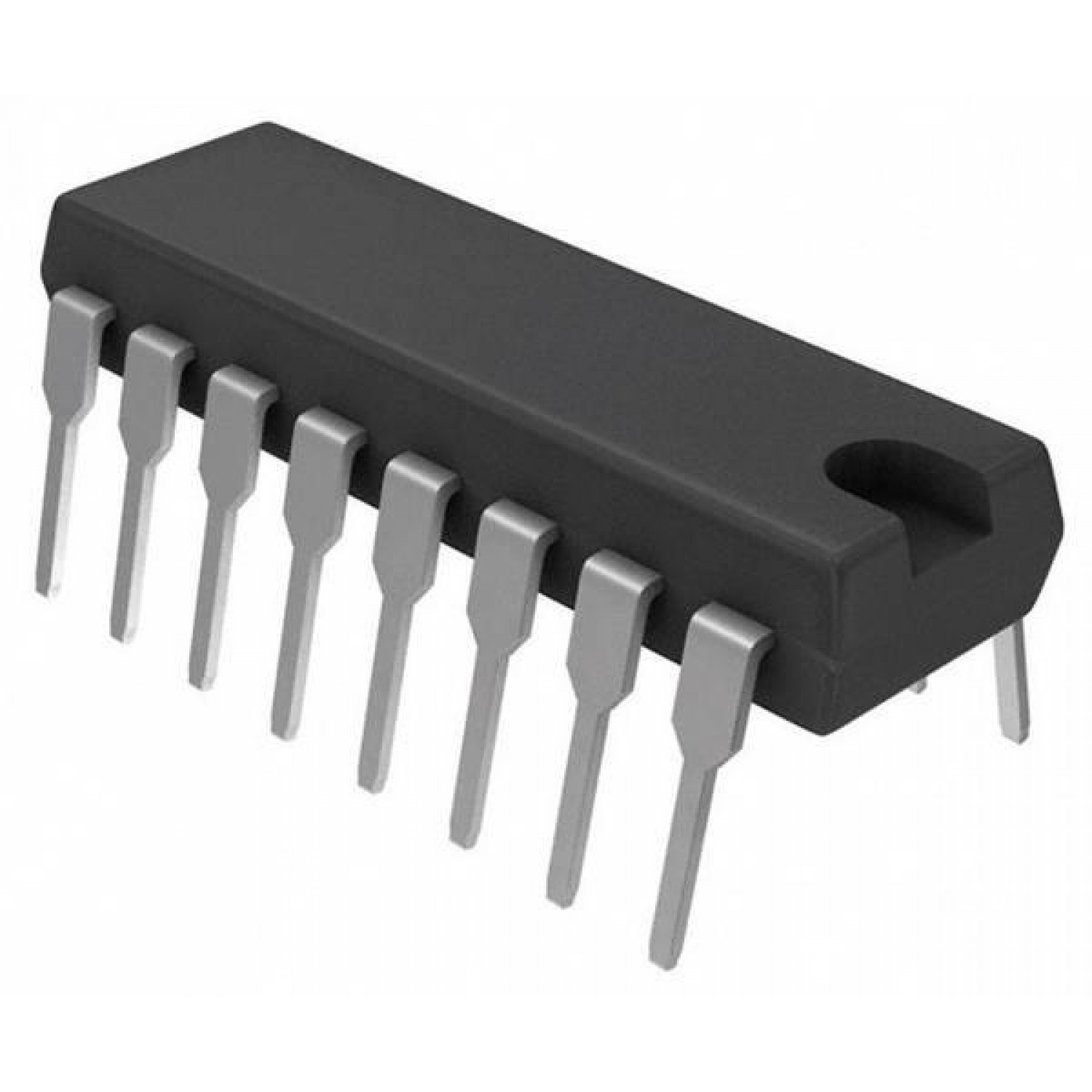
MC145027P Decoder DIP-16 (MC145027P DIP IC)
The MC145027P is a low-power CMOS integrated circuit designed to complement the MC145026 encoder. It is a decoder that interprets a serial digital stream received via RF, infrared, or ultrasonic media and converts it back into parallel output. This IC specifically decodes the first five bits as address information and the remaining four bits as data. If the received address matches the local address set on the pins, the four data bits are transferred to the output latches and the Valid Transmission (VT) pin is pulled high.
This IC is primarily used in secure wireless control, receiver units for garage doors, and remote monitoring systems. It is a fundamental component for Arduino electronics projects in India that involve building custom wireless receivers, multi-channel remote switching, or decentralized control systems where multiple receivers must respond to specific encoded commands.
Key Features
- Decodes 5 address bits and 4 data bits
- Low power consumption (CMOS technology)
- Wide operating supply voltage (4.5V to 18V)
- Built-in error checking (requires two consecutive identical words)
- Latched parallel data outputs
- Valid Transmission (VT) flag output
- Internal oscillator requires only two external resistors and one capacitor
- High noise immunity for stable wireless operation
Specifications
- IC Type = Remote Control Decoder
- Supply Voltage = 4.5V to 18V (5V or 9V typical)
- Quiescent Current = 25uA (Typical at 5V)
- Data Output Current = 10mA (Maximum)
- Oscillator Frequency Range = Up to 500kHz
- Logic Family = CMOS
- Package Type = DIP
- Number of Pins = 16
- Mounting Type = Through-Hole
- Operating Temperature = -40 to 85 degrees Celsius
Interfaces
- PIN 1 to 5 (ADDRESS IN) = Trinary Address Input Bits
- PIN 6 (DIN) = Serial Data Input
- PIN 7 (RS1) = External Resistor 1 for Timing
- PIN 8 (VSS) = Ground (0V)
- PIN 9 (RS2) = External Resistor 2 for Timing
- PIN 10 (C1) = External Capacitor 1 for Timing
- PIN 11 (VT) = Valid Transmission Output (Active High)
- PIN 12 to 15 (DATA OUT) = Latched Parallel Data Outputs
- PIN 16 (VDD) = Positive Supply Voltage