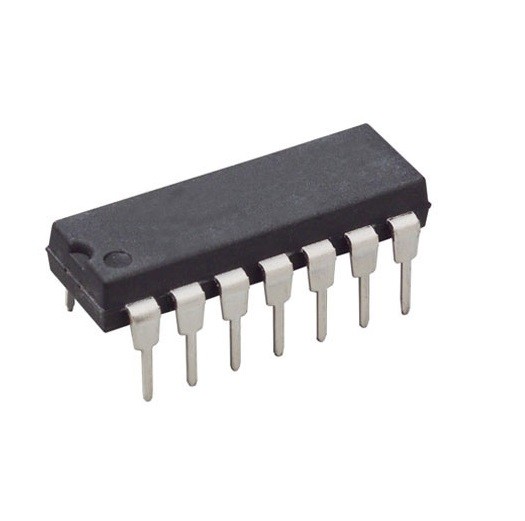
MC1495 Wideband Monolithic Four-Quadrant Multiplier DIP-14 (MC1495 DIP IC)
The MC1495 is a high-precision monolithic four-quadrant multiplier designed for use in applications where the output voltage is a linear product of two input voltages. It features high linearity, excellent temperature stability, and a wide bandwidth. This IC is engineered to perform multiplication, division, squaring, and square root functions with high accuracy. It operates by producing an output current proportional to the product of the differential input voltages at the X and Y inputs.
This IC is primarily used in analog computation, frequency doubling, electronic gain control, and balanced modulation/demodulation. It is a specialized component for Arduino electronics projects in India involving analog signal processing, DIY synthesizer modules (ring modulators), and advanced communication circuits requiring precise signal mixing.
Key Features
- Four-quadrant multiplication (positive and negative inputs)
- Excellent linearity (1.0 percent typical error for X-input)
- Wide bandwidth (operation up to several megahertz)
- Adjustable scale factor via external resistors
- High common-mode rejection (typically 85dB)
- Complementary current outputs for differential processing
- Wide power supply range (+/- 15V typical)
- Versatile functionality including squaring and division
Specifications
- IC Type = Four-Quadrant Analog Multiplier
- Linearity = 1.0 percent (X), 2.0 percent (Y)
- Supply Voltage = +/- 15V (Typical)
- Input Voltage Range = +/- 10V
- Output Current = 1.0mA (Typical)
- Package Type = DIP
- Number of Pins = 14
- Mounting Type = Through-Hole
- Operating Temperature = 0 to 70 degrees Celsius
Interfaces
- PIN 1 (X-INPUT 1) = Differential X-Input (+)
- PIN 2 (X-INPUT 2) = Differential X-Input (-)
- PIN 4 (Y-INPUT 1) = Differential Y-Input (+)
- PIN 8 (Y-INPUT 2) = Differential Y-Input (-)
- PIN 13 (OUTPUT 1) = Differential Current Output 1
- PIN 14 (OUTPUT 2) = Differential Current Output 2
- PIN 3 (X-GAIN) = External Resistor for X-Gain Adjustment
- PIN 10 (Y-GAIN) = External Resistor for Y-Gain Adjustment
- PIN 5 (GND) = Circuit Ground
- PIN 11 (V-) = Negative Supply Voltage
- PIN 12 (V+) = Positive Supply Voltage