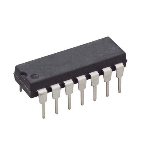
MC1496P Balanced Modulator-Demodulator DIP-14 (MC1496P DIP IC)
The MC1496P is a double-balanced monolithic integrated circuit designed for use in various modulator and demodulator applications. It features high carrier suppression, high common-mode rejection, and excellent frequency response. This IC is engineered to produce an output voltage that is the product of two input voltages (the carrier and the modulating signal). It is widely recognized for its ability to suppress the carrier signal, making it a cornerstone for generating Double Sideband Suppressed Carrier (DSB-SC) signals.
This IC is primarily used in AM and FM modulators, SSB product detectors, frequency doublers, and phase detectors. It is a legendary and essential component for Arduino electronics projects in India involving DIY radio transmitters, ham radio equipment, analog signal mixers, and building custom SDR (Software Defined Radio) front-ends.
Key Features
- Excellent carrier suppression (typically 65dB at 0.5MHz)
- High common-mode rejection (typically 85dB)
- Adjustable gain and signal handling capability
- Balanced inputs and outputs for noise immunity
- Operates at frequencies from DC up to 100MHz
- Low power consumption and low drift
- Versatile operation in single or dual supply modes
- Internal bias circuitry for stable performance
Specifications
- IC Type = Double-Balanced Modulator / Demodulator
- Carrier Suppression = 65dB (at 500kHz)
- Transconductance Bandwidth = 100MHz
- Supply Voltage = +/- 12V (Typical) or 24V (Single)
- Input Voltage Range = +/- 5V
- Differential Output Voltage Swing = 8.0V peak-to-peak (Typical)
- Package Type = DIP
- Number of Pins = 14
- Mounting Type = Through-Hole
- Operating Temperature = 0 to 70 degrees Celsius
Interfaces
- PIN 1 (SIGNAL IN) = Modulating Signal Input (-)
- PIN 4 (SIGNAL IN) = Modulating Signal Input (+)
- PIN 5 (GAIN ADJ) = Connection for External Gain Setting Resistor
- PIN 6 (OUTPUT) = Balanced Modulated Output (+)
- PIN 7 (V-) = Negative Supply Voltage
- PIN 8 (CARRIER IN) = Carrier Signal Input (+)
- PIN 10 (CARRIER IN) = Carrier Signal Input (-)
- PIN 12 (OUTPUT) = Balanced Modulated Output (-)
- PIN 14 (V+) = Positive Supply Voltage