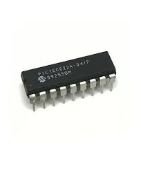
PIC16C622A-04/P 8-Bit CMOS Microcontroller with Analog Comparators DIP-18 (PIC16C622A-04/P DIP IC)
The PIC16C622A-04/P is a high-performance 8-bit CMOS microcontroller belonging to the mid-range PIC family. It utilizes a powerful RISC architecture with only 35 single-word instructions. This specific variant is optimized for 4MHz operation and includes 2048 words of OTP (One-Time Programmable) EPROM program memory and 128 bytes of RAM. A defining feature of this IC is its dual analog comparator module with a programmable voltage reference, allowing for precise analog signal monitoring without the need for an external ADC in many applications. It provides 13 bidirectional I/O pins and a flexible interrupt structure in a standard 18-pin DIP package.
This IC is primarily used in smart energy meters, automotive security systems, and high-performance battery chargers. It is a reliable component for electronics projects in India for building custom voltage window detectors, advanced DIY alarm systems, and learning mid-range PIC assembly programming with integrated analog peripherals.
Key Features
- High-performance RISC CPU with 35 single-word instructions
- Dual analog comparators with programmable on-chip voltage reference
- 2048 words of OTP EPROM program memory
- 13 bidirectional I/O pins with individual direction control
- 8-bit real-time clock/counter (TMR0) with 8-bit programmable prescaler
- Watchdog Timer (WDT) with independent on-chip RC oscillator
- Brown-out Reset (BOR) and Power-on Reset (POR)
- High current source/sink for direct LED drive (25mA)
- Low power consumption (under 2mA at 5V, 4MHz)
Specifications
- IC Type = 8-Bit CMOS Microcontroller (OTP)
- Program Memory = 2048 Words (3.5KB)
- Data RAM = 128 Bytes
- Maximum Speed = 4MHz
- I/O Pins = 13 (Ports A and B)
- Supply Voltage = 2.5V to 5.5V (5V Typical)
- Current Sink/Source = 25mA
- Package Type = PDIP-18
- Number of Pins = 18
- Mounting Type = Through-Hole
- Operating Temperature = 0 to 70 degrees Celsius
Interfaces
- PIN 1 to 4 (RA2, RA3, RA4, MCLR) = Port A I/O / Master Clear
- PIN 5 (VSS) = Ground (0V)
- PIN 6 to 13 (RB0 to RB7) = 8-Bit Port B I/O
- PIN 14 (VDD) = Positive Supply Voltage (5V)
- PIN 15 (OSC2/CLKOUT) = Oscillator Output
- PIN 16 (OSC1/CLKIN) = Oscillator Input
- PIN 17 to 18 (RA0, RA1) = Port A I/O / Comparator Inputs