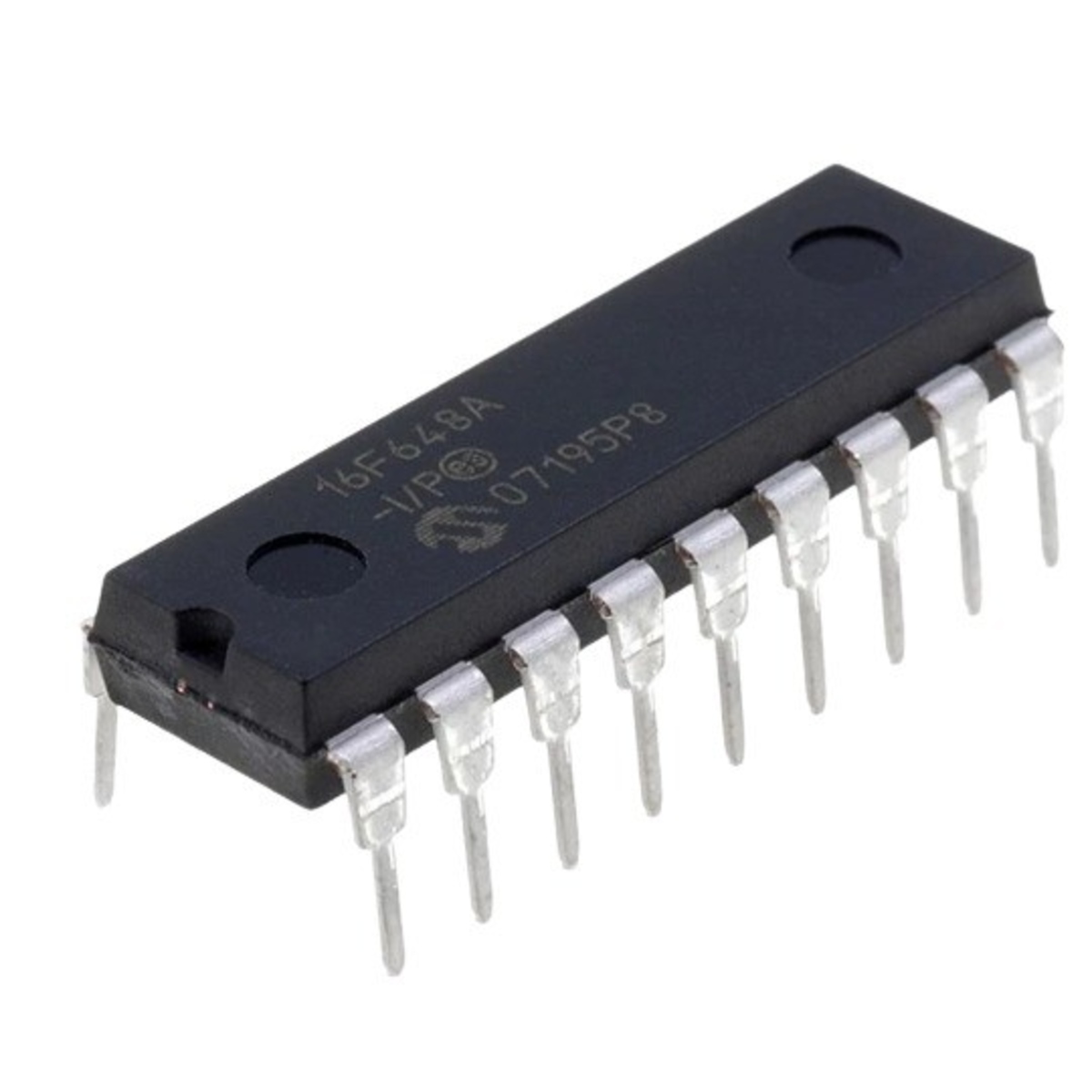
PIC16F648A-I/P 8-Bit Flash Microcontroller with Dual Comparators DIP-18 (PIC16F648A-I/P DIP IC)
The PIC16F648A-I/P is a high-performance, 8-bit Flash-based microcontroller from Microchip’s mid-range family. It serves as the highest-memory variant in the popular PIC16F627A/628A series, offering 7KB of Flash program memory and 256 bytes of RAM. It features a powerful RISC architecture with 35 single-word instructions. A key advantage of this IC is its integrated precision internal 4MHz RC oscillator, which allows for a complete system design without external timing components. It includes a Capture/Compare/PWM (CCP) module, a Universal Asynchronous Receiver Transmitter (UART), and dual analog comparators, providing a comprehensive feature set in a compact 18-pin DIP package.
This IC is primarily used in complex smart home appliances, industrial security systems, and automotive control units requiring larger code space. It is a staple component for Arduino electronics projects in India for building DIY data loggers, advanced serial communication interfaces, and custom timing controllers that need more program memory than the PIC16F628A in a standard 18-pin DIP footprint.
Key Features
- High-performance RISC CPU with 35 single-word instructions
- Internal 4MHz RC oscillator (precision calibrated)
- 7KB Flash program memory for more complex applications
- Dual analog comparators with programmable voltage reference
- Capture/Compare/PWM (CCP) module for precise control
- Universal Asynchronous Receiver Transmitter (UART/USART)
- 256 Bytes of high-endurance Data EEPROM (1,000,000 cycles)
- In-Circuit Serial Programming (ICSP) via two pins
- Low-power NanoWatt technology for extended battery life
- 16 bidirectional I/O pins with high current drive (25mA)
Specifications
- IC Type = 8-Bit Flash Microcontroller
- Program Memory = 7KB (4096 Words)
- Data RAM = 256 Bytes
- Data EEPROM = 256 Bytes
- Speed = 4MHz (Internal) / 20MHz (External)
- I/O Pins = 16 (Ports A and B)
- Supply Voltage = 2.0V to 5.5V
- Current Sink/Source = 25mA
- Package Type = PDIP-18
- Number of Pins = 18
- Mounting Type = Through-Hole
- Operating Temperature = -40 to 85 degrees Celsius
Interfaces
- PIN 1, 2 (RA2, RA3) = Port A I/O / Analog Comparator Inputs / Vref
- PIN 3 (RA4/T0CKI) = Port A I/O / Timer 0 Clock Input
- PIN 4 (MCLR/VPP) = Master Clear / Programming Voltage
- PIN 5 (VSS) = Ground (0V)
- PIN 6 to 13 (RB0 to RB7) = 8-Bit Port B / UART (TX/RX) / CCP1 / External Interrupts
- PIN 14 (VDD) = Positive Supply Voltage (5V)
- PIN 15, 16 (OSC2, OSC1) = Oscillator Output/Input
- PIN 17, 18 (RA0, RA1) = Port A I/O / Analog Comparator Inputs