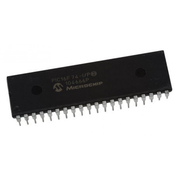
PIC16F74-I/P 8-Bit Flash Microcontroller with ADC and USART DIP-40 (PIC16F74-I/P DIP IC)
The PIC16F74-I/P is a high-performance, 40-pin 8-bit Flash-based microcontroller from Microchip's mid-range family. It features a powerful RISC architecture with 35 single-word instructions and achieves a fast 200ns instruction execution at 20MHz. This IC offers 7KB of Flash program memory and 192 bytes of RAM. It is highly versatile, featuring an 8-channel 8-bit Analog-to-Digital Converter (ADC), two Capture/Compare/PWM (CCP) modules, and a Universal Synchronous Asynchronous Receiver Transmitter (USART/UART) for robust serial communication. With 33 I/O pins, it provides extensive connectivity for complex system designs in a standard 40-pin DIP package.
This IC is primarily used in industrial automation, multi-sensor monitoring systems, and automotive control units. It is a popular choice for Arduino electronics projects in India for building DIY smart home hubs, multi-peripheral controllers, and advanced embedded systems that require a high number of I/O pins and hardware-based serial communication (UART).
Key Features
- High-performance RISC CPU with 35 single-word instructions
- 8-channel 8-bit Analog-to-Digital Converter (ADC)
- Two Capture/Compare/PWM (CCP) modules
- Universal Synchronous Asynchronous Receiver Transmitter (USART/UART)
- Synchronous Serial Port (SSP) with SPI and I2C modes
- Parallel Slave Port (PSP) for high-speed 8-bit communication
- Three hardware timers (2 x 8-bit, 1 x 16-bit)
- Reprogrammable Flash memory with high endurance
- In-Circuit Serial Programming (ICSP) via two pins
- High current source/sink capability (25mA per I/O)
Specifications
- IC Type = 8-Bit Flash Microcontroller
- Program Memory = 7KB (4096 Words)
- Data RAM = 192 Bytes
- ADC Resolution = 8-Bit (8 Channels)
- Maximum Speed = 20MHz
- I/O Pins = 33 (Each programmable for direction)
- Supply Voltage = 4.0V to 5.5V
- Current Sink/Source = 25mA
- Package Type = PDIP-40
- Number of Pins = 40
- Mounting Type = Through-Hole
- Operating Temperature = -40 to 85 degrees Celsius
Interfaces
- PIN 1 (MCLR/VPP) = Master Clear / Programming Voltage
- PIN 2 to 5, 7 to 10 (RA0 to RA5, RE0 to RE2) = Port A and E / Analog Inputs
- PIN 13, 14 (OSC1, OSC2) = External Crystal/Oscillator Inputs
- PIN 11, 32 (VDD) = Positive Supply Voltage (5V)
- PIN 12, 31 (VSS) = Ground (0V)
- PIN 15 to 18, 23 to 26 (RC0 to RC7) = Port C / Timers / CCP / USART / SPI / I2C
- PIN 19 to 22, 27 to 30 (RD0 to RD7) = 8-Bit Port D / Parallel Slave Port
- PIN 33 to 40 (RB0 to RB7) = 8-Bit Port B I/O (Interrupt-on-change)