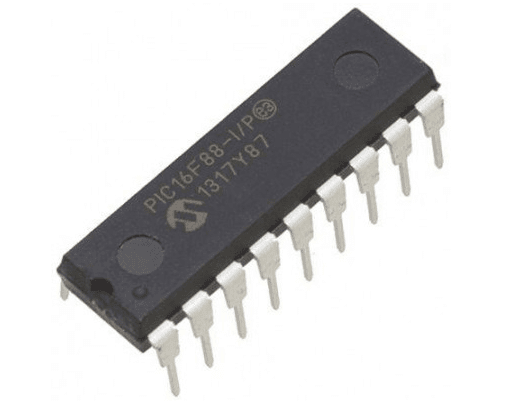
PIC16F88-I/P 8-Bit Flash Microcontroller with NanoWatt Technology DIP-18 (PIC16F88-I/P DIP IC)
The PIC16F88-I/P is one of the most versatile and popular 18-pin microcontrollers in the Microchip mid-range family. It features a powerful RISC architecture with 35 single-word instructions and incorporates "NanoWatt" technology for enhanced power management. This IC includes 7KB of Flash program memory, 256 bytes of RAM, and 256 bytes of high-endurance EEPROM. Key features include an internal 8MHz oscillator (software-configurable), a 7-channel 10-bit Analog-to-Digital Converter (ADC), a Capture/Compare/PWM (CCP) module, and an Addressable USART. Its high level of integration makes it a perfect upgrade for older 18-pin PIC devices like the PIC16F84A.
This IC is primarily used in low-power wireless sensors, handheld medical instruments, and automotive control systems. It is an essential component for Arduino electronics projects in India for building DIY data loggers, advanced motor controllers, and smart embedded systems that require internal oscillators and non-volatile data storage in a compact 18-pin DIP package.
Key Features
- High-performance RISC CPU with 35 instructions
- Internal oscillator block with 8 selectable frequencies (31kHz to 8MHz)
- 7-channel 10-bit Analog-to-Digital Converter (ADC)
- 256 Bytes of high-endurance Data EEPROM (1,000,000 cycles)
- Capture/Compare/PWM (CCP) module
- Addressable USART (Universal Synchronous Asynchronous Receiver Transmitter)
- Synchronous Serial Port (SSP) supporting SPI and I2C modes
- Three hardware timers (2 x 8-bit, 1 x 16-bit)
- NanoWatt technology for ultra-low power consumption
- In-Circuit Serial Programming (ICSP) and In-Circuit Debug (ICD) support
Specifications
- IC Type = 8-Bit Flash Microcontroller
- Program Memory = 7KB (4096 Words)
- Data RAM = 256 Bytes
- Data EEPROM = 256 Bytes
- ADC Resolution = 10-Bit (7 Channels)
- Maximum Speed = 20MHz (External) / 8MHz (Internal)
- I/O Pins = 16 (Each programmable for direction)
- Supply Voltage = 2.0V to 5.5V
- Package Type = PDIP-18
- Number of Pins = 18
- Mounting Type = Through-Hole
- Operating Temperature = -40 to 85 degrees Celsius
Interfaces
- PIN 1, 2, 17, 18 (RA2 to RA0, RA1) = Port A / Analog Inputs / Vref
- PIN 3 (RA4/T0CKI) = Port A I/O / Timer 0 Clock Input
- PIN 4 (MCLR/VPP) = Master Clear / Programming Voltage
- PIN 5 (VSS) = Ground (0V)
- PIN 6 to 13 (RB0 to RB7) = 8-Bit Port B / USART / CCP / SPI / I2C
- PIN 14 (VDD) = Positive Supply Voltage (5V)
- PIN 15, 16 (OSC2, OSC1) = Oscillator Output/Input