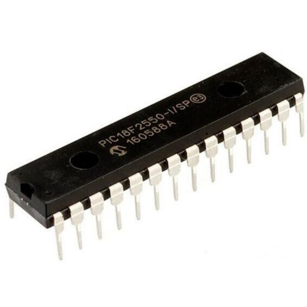
PIC18F2550-I/SP 8-Bit Flash Microcontroller with Full-Speed USB DIP-28 (PIC18F2550-I/SP DIP IC)
The PIC18F2550-I/SP is a flagship 8-bit Flash-based microcontroller from Microchip's advanced PIC18 family, specifically designed for high-performance connectivity. Housed in a 28-pin Skinny DIP package, it is world-renowned for its integrated Full-Speed USB 2.0 interface (12 Mbit/s), which includes an on-chip transceiver and voltage regulator. It features a powerful RISC architecture with 75 instructions and can operate at speeds up to 48MHz (12 MIPS) using its internal Phase Locked Loop (PLL). With 32KB of Flash program memory, 2KB of RAM (including 1KB of dual-access RAM for USB), and 256 bytes of EEPROM, it offers a robust platform for data-intensive applications. Its specialized oscillator structure and nanoWatt power management make it a premier choice for "legacy-free" designs that interface directly with modern PCs.
This IC is the industry standard for building DIY USB peripherals in India, such as custom HID game controllers, USB-to-Serial converters, and bootloader-based development boards. It is an essential component for Arduino electronics projects for building PC-linked data loggers, secure hardware dongles, and smart instrumentation tools that require plug-and-play USB connectivity in a 28-pin DIP footprint.
Key Features
- High-performance RISC CPU with 75 instructions (C-compiler optimized)
- Integrated Full-Speed USB 2.0 Module (12 Mbit/s) with 16 Endpoints
- 1KB Dual-Access RAM dedicated for USB buffering
- Hardware 8x8 Single-Cycle Multiplier for accelerated math
- 32KB Flash program memory (10,000 erase/write cycles)
- 10-channel 10-bit Analog-to-Digital Converter (ADC)
- Enhanced Capture/Compare/PWM (ECCP) with up to 4 outputs
- Dual Analog Comparators with programmable voltage reference
- Internal Oscillator Block (31kHz to 8MHz) with 48MHz PLL for USB
- nanoWatt Technology for eXtreme Low Power management
Specifications
- IC Type = 8-Bit Flash Microcontroller with USB
- Program Memory = 32KB (16384 Words)
- Data RAM = 2048 Bytes (2KB)
- Data EEPROM = 256 Bytes
- ADC Resolution = 10-Bit (10 Channels)
- Maximum Speed = 48MHz (12 MIPS)
- I/O Pins = 24 (Each programmable for direction)
- Supply Voltage = 4.2V to 5.5V
- Current Sink/Source = 25mA
- Package Type = SPDIP-28 (Skinny DIP)
- Number of Pins = 28
- Mounting Type = Through-Hole
- Operating Temperature = -40 to 85 degrees Celsius
Interfaces
- PIN 1 (MCLR/VPP/RE3) = Master Clear / Programming Voltage
- PIN 2 to 5 (RA0 to RA3) = Port A / Analog Inputs / USB Vref
- PIN 6 (RA4) = Port A I/O / External Clock Input
- PIN 7 (RA5) = Port A I/O / Analog Input / LVD
- PIN 8, 19 (VSS) = Ground (0V)
- PIN 9, 10 (OSC1, OSC2) = External Crystal/Oscillator Inputs
- PIN 11 to 13 (RC0 to RC2) = Port C / Timers / CCP / USB OE
- PIN 14 to 16 (VUSB, RC4, RC5) = USB Voltage / USB D- / USB D+
- PIN 17, 18 (RC6, RC7) = Port C / USART (TX/RX)
- PIN 20 (VDD) = Positive Supply Voltage (5V)
- PIN 21 to 28 (RB0 to RB7) = 8-Bit Port B / External Interrupts / ICSP