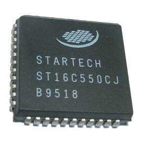
ST16C550CJ Universal Asynchronous Receiver and Transmitter (UART) with FIFO PLCC-44 (ST16C550CJ PLCC-44 IC) The ST16C550CJ is a high-performance Universal Asynchronous Receiver and Transmitter (UART) designed for high-speed serial communications. This IC features a 16-byte Transmit and Receive FIFO (First-In, First-Out) buffer, which significantly reduces the CPU overhead by allowing the processor to handle data in bursts rather than byte-by-byte. It is a functional replacement for the industry-standard 16450 and 8250 UARTs, offering enhanced data rates up to 1.5 Mbps. The device manages the conversion of parallel data from the CPU into a serial bit stream for transmission and vice versa, handling all necessary timing, parity, and framing.
This IC is primarily used in industrial serial interfaces (RS-232/RS-485), high-speed modems, and embedded computer systems. It is a specialized component for advanced electronics projects in India involving custom serial expansion boards for microcontrollers, legacy PC hardware repair, and building high-reliability communication bridges for industrial automation.
Key Features
- 16-byte Transmit and Receive FIFOs to prevent data loss
- Fully software compatible with 16450 and 8250 UARTs
- Programmable baud rate generator from 50 to 1.5 Mbps
- Complete status reporting capabilities (Error, Line, and Modem status)
- Independent receiver clock input for asynchronous operation
- Support for 5, 6, 7, and 8-bit characters
- Built-in diagnostic loopback mode for testing
- Fully prioritized interrupt system control
Specifications
- IC Type = UART with FIFO
- Data Rate = Up to 1.5 Mbps
- FIFO Depth = 16-Byte (TX and RX)
- Supply Voltage (VCC) = 2.97V to 5.50V (5V Typical)
- Logic Interface = 8-Bit Parallel
- Modem Control = Full (CTS, RTS, DSR, DTR, RI, CD)
- Package Type = PLCC-44
- Number of Pins = 44
- Mounting Type = Surface Mount / Socket (Through-Hole)
- Operating Temperature = 0 to 70 degrees Celsius
Interfaces
- PIN 1 (VCC) = Positive Supply Voltage (5V)
- PIN 2 to 9 (D0 to D7) = 8-Bit Parallel Data Bus
- PIN 12 (TX) = Serial Data Output
- PIN 14 (RX) = Serial Data Input
- PIN 22 (GND) = Ground (0V)
- PIN 25 to 30 (A0 to A2, CS0 to CS2) = Address and Chip Select Pins
- PIN 32 to 34 (IOR, IOW) = Read and Write Control Signals
- PIN 36 to 41 (CTS, RTS, DSR, DTR, RI, CD) = Modem Control Signals