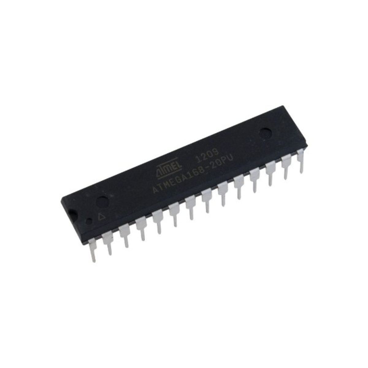
ATMEGA168-20PU 8-Bit High-Performance AVR Microcontroller DIP-28 (ATMEGA168-20PU IC)
The ATMEGA168-20PU is a popular, low-power 8-bit AVR RISC-based microcontroller from Microchip (formerly Atmel). Housed in a 28-pin DIP package, it balances memory and peripheral options in a compact through-hole format. It features 16KB of Flash memory, 512 bytes of EEPROM, and 1KB of SRAM. This specific "-20PU" variant is rated for a clock speed of up to 20MHz and operates within the standard industrial temperature range.
This IC is a staple in India for embedded systems development, robotics, and industrial automation projects. It is essentially a smaller-memory sibling to the famous ATmega328P (used in the Arduino Uno), making it a cost-effective choice for designs that don't require 32KB of code space but still need high-speed processing and a rich set of peripherals like I2C, SPI, and UART.
Key Features
- High Performance, Low Power: Executes most instructions in a single clock cycle, achieving throughputs near 1 MIPS per MHz.
- picoPower Technology: Optimized for battery-operated devices with ultra-low power consumption in sleep modes.
- Versatile Peripherals: Includes 6 PWM channels, an 8-channel 10-bit ADC, and three flexible timers with compare modes.
- Enhanced Security: Features a programmable watchdog timer with an independent internal oscillator to prevent system lock-ups.
- In-System Programmable: Can be reprogrammed easily via the SPI port, supporting both specialized programmers and on-chip boot codes.
- Flexible Voltage: Operates reliably across a wide supply voltage range from 2.7V to 5.5V.
Specifications
- IC Type: 8-Bit Microcontroller (MCU)
- Core: AVR
- Flash Memory: 16 KB
- EEPROM / SRAM: 512 Bytes / 1024 Bytes
- Maximum Speed: 20 MHz
- I/O Pins: 23 Programmable I/O Lines
- A/D Converter: 6-channel 10-bit (in PDIP package)
- Package Type: PDIP-28 (0.300", 7.62mm width)
- Mounting Type: Through-Hole
- Operating Temperature: -40 to +85 degrees Celsius
Pinout Configuration (28-Pin DIP)
- Pin 1 (PC6/RESET): Reset Input (Active Low)
- Pin 2 (PD0/RXD): USART Data Input
- Pin 3 (PD1/TXD): USART Data Output
- Pin 4 (PD2/INT0): External Interrupt 0
- Pin 5 (PD3/INT1): External Interrupt 1
- Pin 6 (PD4/T0): Timer/Counter0 External Counter Input
- Pin 7 (VCC): Digital Supply Voltage
- Pin 8 (GND): Ground
- Pin 9 (PB6/XTAL1): Crystal Oscillator Input
- Pin 10 (PB7/XTAL2): Crystal Oscillator Output
- Pin 11 (PD5/T1): Timer/Counter1 External Counter Input
- Pin 12 (PD6/AIN0): Analog Comparator Positive Input
- Pin 13 (PD7/AIN1): Analog Comparator Negative Input
- Pin 14 (PB0/ICP1): Timer/Counter1 Input Capture Pin
- Pin 15 (PB1/OC1A): Timer/Counter1 Output Compare A Match
- Pin 16 (PB2/OC1B): Timer/Counter1 Output Compare B Match
- Pin 17 (PB3/MOSI): SPI Master Out Slave In
- Pin 18 (PB4/MISO): SPI Master In Slave Out
- Pin 19 (PB5/SCK): SPI Clock
- Pin 20 (AVCC): Supply Voltage for ADC
- Pin 21 (AREF): Analog Reference for ADC
- Pin 22 (GND): Ground
- Pin 23 (PC0/ADC0): ADC Channel 0
- Pin 24 (PC1/ADC1): ADC Channel 1
- Pin 25 (PC2/ADC2): ADC Channel 2
- Pin 26 (PC3/ADC3): ADC Channel 3
- Pin 27 (PC4/SDA): I2C Data I/O / ADC Channel 4
- Pin 28 (PC5/SCL): I2C Clock / ADC Channel 5