H11A1 Transistor Output Optocoupler DIP-6 (H11A1 DIP IC)
The H11A1 is a high-performance general-purpose optoisolator designed to provide complete electrical isolation between input and output circuits. It consists of a Gallium Arsenide (GaAs) infrared-emitting diode optically coupled to a monolithic silicon phototransistor detector. This IC is engineered to transfer signals across an isolation barrier, protecting low-voltage control circuitry from high-voltage transients and ground loops. It features a high current transfer ratio (CTR) of 50 percent minimum, ensuring reliable signal transmission even with low input currents.
This IC is primarily used in power supply regulators, digital logic inputs, and industrial microprocessor interfaces. It is a fundamental component for Arduino electronics projects in India for isolating 5V microcontrollers from 12V or 24V DC loads, building AC zero-crossing detectors (when used with appropriate bridge rectifiers), and preventing electrical noise from affecting sensitive sensors.
Key Features
- High isolation voltage (up to 5300 Vrms)
- Minimum 50 percent current transfer ratio (CTR)
- High-voltage phototransistor (up to 30V VCEO)
- Fast switching speeds (typically 2-3 microseconds)
- Low coupling capacitance (typically 0.5pF)
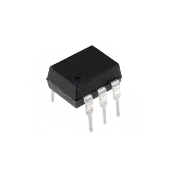
- Standard 6-pin DIP package for easy through-hole mounting
- UL recognized and highly reliable for industrial use
- Compatible with TTL and CMOS logic levels
Specifications
- IC Type = Phototransistor Optocoupler
- Isolation Voltage = 5300 Vrms
- Forward Current (If) = 60mA (Maximum)
- Collector-Emitter Voltage (VCEO) = 30V
- Collector Current (Ic) = 100mA (Maximum)
- Current Transfer Ratio (CTR) = 50 percent (Minimum)
- Package Type = DIP-6
- Number of Pins = 6
- Mounting Type = Through-Hole
- Operating Temperature = -55 to 100 degrees Celsius
Interfaces
- PIN 1 (ANODE) = Infrared LED Anode (+)
- PIN 2 (CATHODE) = Infrared LED Cathode (-)
- PIN 3 (NC) = No Connection
- PIN 4 (EMITTER) = Phototransistor Emitter
- PIN 5 (COLLECTOR) = Phototransistor Collector
- PIN 6 (BASE) = Phototransistor Base (Optional connection for biasing)