HT12E and HT12D RF Remote Control Encoder/Decoder Pair (HT12E + HT12D 1 PAIR DIP IC)
The HT12E and HT12D pair is the industry standard solution for building simple, reliable wireless remote control systems. This pair consists of one HT12E (Encoder) and one HT12D (Decoder). The HT12E converts 4-bit parallel data into a serial stream for transmission, while the HT12D receives this serial stream and converts it back into 4-bit parallel data. Both ICs feature 8 address bits, allowing for up to 256 unique security codes to prevent interference between multiple systems. They are designed to work seamlessly with 315MHz or 433MHz RF transmitter and receiver modules.
This pair is primarily used in wireless doorbells, remote-controlled toy cars, and security alarms. It is the most popular choice for Arduino electronics projects in India for creating wireless 4-channel switching, remote-controlled robots, and home automation systems without needing complex microcontroller coding for the wireless protocol.
Key Features
- Complete 4-channel wireless link solution (Encoder + Decoder)
- 8-bit address and 4-bit data configuration for security
- Wide operating voltage range (2.4V to 12V)
- Low power consumption and high noise immunity CMOS technology
- Built-in oscillators requiring only one external resistor each
- Valid Transmission (VT) indicator pin on the HT12D decoder
- Easy interface with RF (433MHz/315MHz) or Infrared (IR) modules
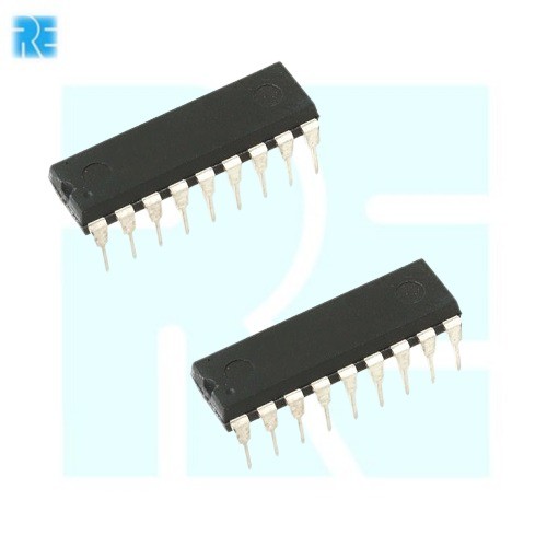
- Robust 18-pin DIP packages for easy breadboard prototyping
Specifications
- IC Set = 1 x HT12E (Encoder) and 1 x HT12D (Decoder)
- Operating Voltage = 2.4V to 12.0V
- Standby Current = 0.1uA to 1uA
- Addressing = 8-Bit (256 combinations)
- Data Channels = 4-Bit Parallel
- Transmission Media = RF (ASK/OOK) or Infrared
- Package Type = DIP-18 (Both ICs)
- Mounting Type = Through-Hole
- Operating Temperature = -20 to 75 degrees Celsius
Interfaces (HT12E Encoder)
- PIN 1 to 8 (A0 to A7) = 8-Bit Address Inputs
- PIN 10 to 13 (AD8 to AD11) = 4-Bit Data Inputs
- PIN 14 (TE) = Transmit Enable (Active Low)
- PIN 17 (DOUT) = Serial Data Output to Transmitter
- PIN 18 (VDD) = Positive Supply (2.4V-12V)
- PIN 9 (VSS) = Ground (0V)
Interfaces (HT12D Decoder)
- PIN 1 to 8 (A0 to A7) = 8-Bit Address Inputs
- PIN 10 to 13 (D8 to D11) = 4-Bit Data Outputs
- PIN 14 (DIN) = Serial Data Input from Receiver
- PIN 17 (VT) = Valid Transmission LED Indicator Output
- PIN 18 (VDD) = Positive Supply (2.4V-12V)
- PIN 9 (VSS) = Ground (0V)