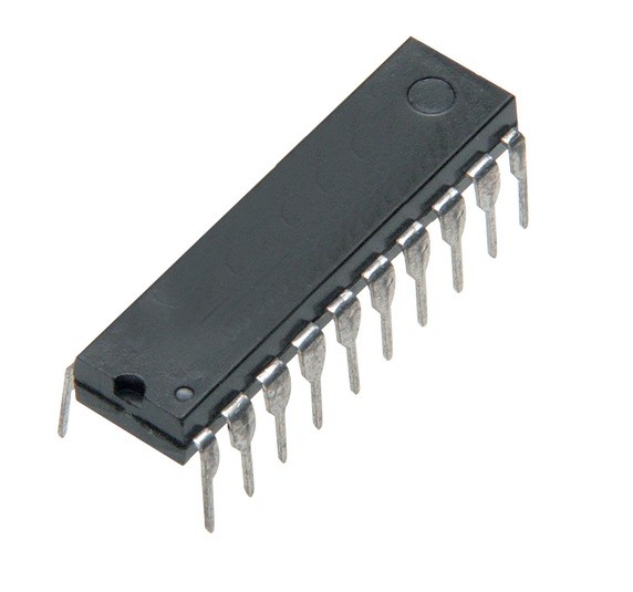
MC145407P 5V RS-232 Driver/Receiver DIP-20 (MC145407P DIP IC)
The MC145407P is a silicon-gate CMOS integrated circuit designed to fulfill the electrical specifications of EIA-232-E and CCITT V.28 standards while operating from a single 5V power supply. This IC combines three drivers and three receivers in one package. It features an on-board 20 kHz oscillator and a dual charge pump architecture (voltage doubler and inverter) that converts the 5V input into the +/- 10V rails required for RS-232 communication. This eliminates the need for multiple power supplies and requires only four inexpensive external electrolytic capacitors.
This IC is primarily used in computer serial ports, modem interfaces, and industrial data communication links. It is a robust component for Arduino electronics projects in India that require multi-channel RS-232 level shifting, allowing a 5V microcontroller to communicate with multiple pieces of legacy industrial equipment, PLCs, or vintage computer peripherals.
Key Features
- Operates from a single 5V power supply
- Triple drivers and triple receivers in one package
- Internal charge pumps generate +/- 10V from 5V
- Drivers provide +/- 7.5V output swing (typical)
- Receivers feature 0.8V hysteresis for high noise immunity
- TTL and CMOS compatible inputs
- Driver output current limiting and 300 ohm power-off impedance
- Low power consumption (1.2mA quiescent current)
- Slew rate limited output (4V/us to 30V/us)
Specifications
- IC Type = RS-232 Driver/Receiver (Transceiver)
- Number of Drivers = 3
- Number of Receivers = 3
- Supply Voltage (VCC) = 4.5V to 5.5V
- Internal Voltage Generation = +/- 10V (Dual Charge Pump)
- Logic Family = CMOS / TTL Compatible
- Package Type = Plastic DIP
- Number of Pins = 20
- Mounting Type = Through-Hole
- Operating Temperature = -40 to 85 degrees Celsius
Interfaces
- PIN 19 (VCC) = Positive Supply Voltage (5V)
- PIN 2 (GND) = Ground (0V)
- PIN 20 (C1+) = External Capacitor 1 (+)
- PIN 18 (C1-) = External Capacitor 1 (-)
- PIN 1 (C2+) = External Capacitor 2 (+)
- PIN 3 (C2-) = External Capacitor 2 (-)
- PIN 17 (VDD) = Doubled Voltage Output (+10V)
- PIN 4 (VSS) = Inverted Voltage Output (-10V)
- PIN 15, 13, 11 (DI1, DI2, DI3) = Driver Logic Inputs
- PIN 6, 8, 10 (TX1, TX2, TX3) = RS-232 Driver Outputs
- PIN 5, 7, 9 (RX1, RX2, RX3) = RS-232 Receiver Inputs
- PIN 16, 14, 12 (DO1, DO2, DO3) = Receiver Logic Outputs