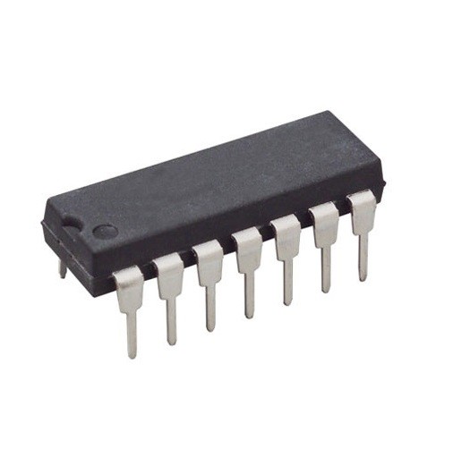
MC1488N Quad Line Driver DIP-14 (MC1488N DIP IC)
The MC1488N is a monolithic quad line driver designed to interface data terminal equipment (DTE) with data communications equipment (DCE) in accordance with the EIA RS-232C standard. This IC contains four independent drivers that convert TTL/DTL input logic levels into high-voltage bipolar signals required for serial communication. It is a classic telecommunications component known for its reliability in driving capacitive loads and providing output current limiting.
This IC is primarily used in RS-232 serial ports, computer-to-peripheral interfaces, and modem data transmission. It is a fundamental component for Arduino electronics projects in India involving legacy serial communication, interfacing microcontrollers with older industrial equipment, or building custom RS-232 to TTL level shifters (when paired with an MC1489 receiver).
Key Features
- Quad line drivers in a single 14-pin package
- Full compliance with RS-232C standard specifications
- Current limited output (typically 10mA)
- Output resistance remains above 300 ohms when power is off
- Wide supply voltage range (+/- 9V to +/- 15V)
- Compatible with DTL and TTL input logic levels
- Simple slew rate control with an external capacitor
- High output voltage swing for long-distance communication
Specifications
- IC Type = Quad Line Driver (RS-232)
- Logic Family = TTL / DTL Compatible
- Supply Voltage = +/- 9V to +/- 15V (Dual)
- Output Voltage Swing = +/- 6V (Minimum at +/- 9V supply)
- Slew Rate = 30V/microsecond (Max without capacitor)
- Package Type = DIP
- Number of Pins = 14
- Mounting Type = Through-Hole
- Operating Temperature = 0 to 75 degrees Celsius
Interfaces
- PIN 1 (V-) = Negative Supply Voltage
- PIN 2 (IN A) = Logic Input A
- PIN 3 (OUT A) = RS-232 Output A
- PIN 4 (IN B1) = Logic Input B1
- PIN 5 (IN B2) = Logic Input B2
- PIN 6 (OUT B) = RS-232 Output B
- PIN 7 (GND) = Ground (0V)
- PIN 8 (OUT C) = RS-232 Output C
- PIN 9 (IN C1) = Logic Input C1
- PIN 10 (IN C2) = Logic Input C2
- PIN 11 (OUT D) = RS-232 Output D
- PIN 12 (IN D) = Logic Input D
- PIN 14 (V+) = Positive Supply Voltage