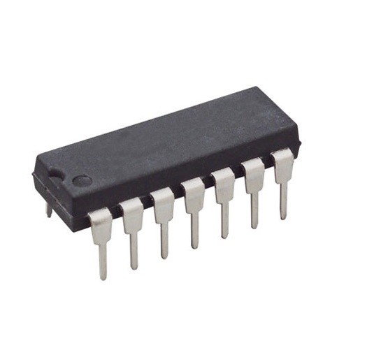
MC1489N Quad Line Receiver DIP-14 (MC1489N DIP IC)
The MC1489N is a monolithic quad line receiver designed to interface data communications equipment (DCE) with data terminal equipment (DTE) in accordance with the EIA RS-232C standard. This IC contains four independent receivers that convert high-voltage bipolar RS-232 signals back into standard TTL/DTL logic levels. It is the complementary receiver to the MC1488N driver and is known for its high input impedance and built-in noise filtering capability.
This IC is primarily used in RS-232 serial ports, computer-to-peripheral interfaces, and modem data reception. It is a fundamental component for Arduino electronics projects in India involving legacy serial communication, allowing modern 5V microcontrollers to safely read data from older industrial equipment, vintage computers, or professional GPS modules.
Key Features
- Quad line receivers in a single 14-pin package
- Full compliance with RS-232C standard specifications
- Integrated input response control for noise filtering
- Built-in input threshold hysteresis for reliable switching
- High input resistance (3k to 7k ohms)
- Logic levels compatible with DTL and TTL systems
- Single 5V supply operation for the receiver section
- Input voltage range up to +/- 30V
Specifications
- IC Type = Quad Line Receiver (RS-232)
- Logic Family = TTL / DTL Compatible
- Supply Voltage = 4.5V to 5.5V (5V Typical)
- Input Voltage Range = +/- 30V (Maximum)
- Input Resistance = 3.0k to 7.0k ohms
- Package Type = DIP
- Number of Pins = 14
- Mounting Type = Through-Hole
- Operating Temperature = 0 to 75 degrees Celsius
Interfaces
- PIN 1 (IN A) = RS-232 Signal Input A
- PIN 2 (RESPONSE A) = Noise Filter / Threshold Control A
- PIN 3 (OUT A) = TTL Logic Output A
- PIN 4 (IN B) = RS-232 Signal Input B
- PIN 5 (RESPONSE B) = Noise Filter / Threshold Control B
- PIN 6 (OUT B) = TTL Logic Output B
- PIN 7 (GND) = Ground (0V)
- PIN 8 (OUT C) = TTL Logic Output C
- PIN 9 (RESPONSE C) = Noise Filter / Threshold Control C
- PIN 10 (IN C) = RS-232 Signal Input C
- PIN 11 (OUT D) = TTL Logic Output D
- PIN 12 (RESPONSE D) = Noise Filter / Threshold Control D
- PIN 13 (NC) = No Connection
- PIN 14 (VCC) = Positive Supply Voltage (5V)