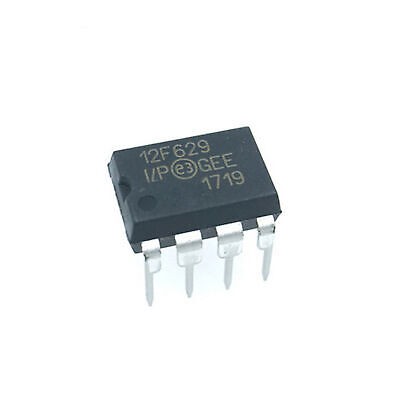
PIC12F629-I/P 8-Bit Flash Microcontroller with Analog Comparator DIP-8 (PIC12F629 I/P DIP IC)
The PIC12F629-I/P is a high-performance, 8-bit Flash-based microcontroller featuring a powerful RISC architecture with 35 single-word instructions. This IC includes 1024 words of Flash program memory, 64 bytes of SRAM, and a dedicated 128 bytes of high-endurance EEPROM for non-volatile data storage. It is equipped with an internal 4MHz precision oscillator and an integrated analog comparator module, making it a highly capable but compact control solution. Its mid-range core supports features like interrupt handling and a deeper hardware stack compared to the baseline series.
This IC is primarily used in smart energy meters, automotive remote controls, and medical monitoring devices. It is a favorite component for Arduino electronics projects in India for building custom EEPROM-based data loggers, advanced LED pulse-width modulation (PWM) controllers, and secure wireless key fobs where data persistence is required.
Key Features
- High-performance RISC CPU with 35 single-word instructions
- 128 Bytes of high-endurance Data EEPROM (1,000,000 cycles)
- Integrated Analog Comparator module with programmable reference
- Internal 4MHz RC oscillator with +/- 1 percent accuracy
- Power-on Reset (POR) and Brown-out Detect (BOD)
- In-Circuit Serial Programming (ICSP) via two pins
- Low power consumption (under 1.0uA standby at 2V)
- Six general-purpose I/O pins with individual direction control
Specifications
- IC Type = 8-Bit Flash Microcontroller with EEPROM
- Program Memory = 1024 Words (1.75KB)
- Data RAM = 64 Bytes
- Data EEPROM = 128 Bytes
- Speed = 4MHz (Internal) / 20MHz (External)
- I/O Pins = 6 (5 I/O, 1 Input-only)
- Supply Voltage = 2.0V to 5.5V
- Package Type = PDIP-8
- Number of Pins = 8
- Mounting Type = Through-Hole
- Operating Temperature = -40 to 85 degrees Celsius
Interfaces
- PIN 1 (VDD) = Positive Supply Voltage (5V)
- PIN 2 (GP5/OSC1/CLKIN) = General Purpose I/O / Oscillator Input
- PIN 3 (GP4/OSC2/AN3/CLKOUT) = General Purpose I/O / Oscillator Output
- PIN 4 (GP3/MCLR/VPP) = Input Only / Master Clear / Programming Voltage
- PIN 5 (GP2/T0CKI/COUT) = General Purpose I/O / Timer Clock Input / Comparator Out
- PIN 6 (GP1/CIN-/ICSPCLK) = General Purpose I/O / Comparator Neg Input / Programming Clock
- PIN 7 (GP0/CIN+/ICSPDAT) = General Purpose I/O / Comparator Pos Input / Programming Data
- PIN 8 (VSS) = Ground (0V)