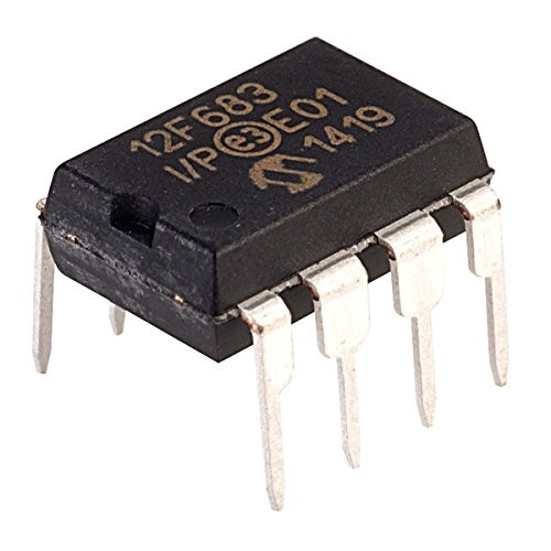
PIC12F683-I/P 8-Bit Flash Microcontroller with PWM and 10-Bit ADC DIP-8 (PIC12F683 I/P DIP IC)
The PIC12F683-I/P is a feature-rich, 8-bit Flash-based microcontroller that represents one of the most powerful options in the 8-pin DIP family. It is built on a mid-range RISC architecture with 35 instructions and provides 2048 words of Flash program memory, 128 bytes of SRAM, and 256 bytes of high-endurance EEPROM. This IC stands out by offering a Capture/Compare/PWM (CCP) module, a 4-channel 10-bit Analog-to-Digital Converter (ADC), and two 8-bit timers plus one 16-bit timer. With its precision internal oscillator and broad feature set, it is designed for sophisticated control applications that require high integration in a minimal footprint.
This IC is primarily used in specialized LED lighting controllers, motor speed regulators, and advanced battery management systems. It is a premium component for Arduino electronics projects in India for building high-resolution DIY servo controllers, complex sensor nodes with data logging, and smart power converters where integrated PWM and analog sensing are critical.
Key Features
- High-performance RISC CPU with 35 single-word instructions
- 10-bit Analog-to-Digital Converter (ADC) with 4-channel multiplexing
- Capture/Compare/PWM (CCP) module for precise pulse generation
- 256 Bytes of high-endurance Data EEPROM (1,000,000 cycles)
- Precision internal oscillator (8MHz to 31kHz, software selectable)
- Three hardware timers (2 x 8-bit, 1 x 16-bit)
- Ultra-low power wake-up and low power consumption (under 1.0uA standby)
- In-Circuit Serial Programming (ICSP) via two pins
- Integrated Analog Comparator with programmable reference
Specifications
- IC Type = 8-Bit Flash Microcontroller with CCP/PWM
- Program Memory = 2048 Words (3.5KB)
- Data RAM = 128 Bytes
- Data EEPROM = 256 Bytes
- ADC Resolution = 10-Bit (4 Channels)
- Speed = 8MHz (Internal) / 20MHz (External)
- I/O Pins = 6 (5 I/O, 1 Input-only)
- Supply Voltage = 2.0V to 5.5V
- Package Type = PDIP-8
- Number of Pins = 8
- Mounting Type = Through-Hole
- Operating Temperature = -40 to 85 degrees Celsius
Interfaces
- PIN 1 (VDD) = Positive Supply Voltage (5V)
- PIN 2 (GP5/T1CKI/OSC1/CLKIN) = General Purpose I/O / Timer 1 Clock Input
- PIN 3 (GP4/AN3/T1G/OSC2/CLKOUT) = General Purpose I/O / Analog Input 3
- PIN 4 (GP3/MCLR/VPP) = Input Only / Master Clear / Programming Voltage
- PIN 5 (GP2/AN2/T0CKI/CCP1/COUT) = General Purpose I/O / PWM Output / Analog Input 2
- PIN 6 (GP1/AN1/CIN-/VREF/ICSPCLK) = General Purpose I/O / Analog Input 1 / Programming Clock
- PIN 7 (GP0/AN0/CIN+/ICSPDAT) = General Purpose I/O / Analog Input 0 / Programming Data
- PIN 8 (VSS) = Ground (0V)