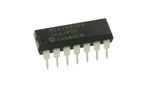
PIC16C505-04/P 8-Bit CMOS Microcontroller DIP-14 (PIC16C505-04/P DIP IC)
The PIC16C505-04/P is a member of the baseline family of 8-bit CMOS microcontrollers from Microchip. It features a high-performance RISC CPU with only 33 single-word instructions and is designed for low-cost, space-sensitive applications. This specific variant operates at a maximum frequency of 4MHz and includes 1024 words of OTP (One-Time Programmable) EPROM program memory and 72 bytes of RAM. It is equipped with an internal 4MHz RC oscillator, which reduces the need for external components, and provides 12 bidirectional I/O pins in a compact 14-pin DIP package.
This IC is primarily used in small appliances, automotive sensors, and low-power remote control systems. It is a reliable component for electronics projects in India for building standalone logic sequencers, dedicated timing circuits, and learning baseline PIC assembly programming on a medium-pin-count platform.
Key Features
- High-performance RISC CPU with 33 single-word instructions
- Internal 4MHz RC oscillator with programmable calibration
- 1024 words of OTP EPROM program memory
- 12 bidirectional I/O pins with individual direction control
- 8-bit real-time clock/counter (TMR0) with 8-bit programmable prescaler
- Watchdog Timer (WDT) with independent on-chip RC oscillator
- Wide operating voltage range (2.5V to 5.5V)
- Low power consumption (under 2mA at 5V, 4MHz)
- High current source/sink for direct LED drive (25mA)
Specifications
- IC Type = 8-Bit CMOS Microcontroller (OTP)
- Program Memory = 1024 Words (1.5KB)
- Data RAM = 72 Bytes
- Maximum Speed = 4MHz
- I/O Pins = 12 (Each programmable for direction)
- Supply Voltage = 2.5V to 5.5V (5V Typical)
- Current Sink/Source = 25mA
- Package Type = PDIP-14
- Number of Pins = 14
- Mounting Type = Through-Hole
- Operating Temperature = 0 to 70 degrees Celsius
Interfaces
- PIN 1 (VDD) = Positive Supply Voltage (5V)
- PIN 2 (RB5/OSC1/CLKIN) = Port B I/O / Oscillator Input
- PIN 3 (RB4/OSC2/CLKOUT) = Port B I/O / Oscillator Output
- PIN 4 (RB3/MCLR/VPP) = Port B Input / Master Clear / Programming Voltage
- PIN 5 to 7 (RB2, RB1, RB0) = 3-Bit Port B I/O
- PIN 8 to 13 (RC5 to RC0) = 6-Bit Port C I/O
- PIN 14 (VSS) = Ground (0V)