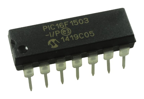
PIC16F1503-I/P 8-Bit Flash Microcontroller with Integrated Configurable Logic DIP-14 (PIC16F1503-I/P DIP IC)
The PIC16F1503-I/P is a highly versatile, low-cost 8-bit Flash-based microcontroller from Microchip’s "Enhanced Mid-range" family, housed in a compact 14-pin package. This IC is designed to provide high performance and low power consumption through its integrated "Core Independent Peripherals" (CIP). It features a powerful RISC architecture with 49 instructions and includes 3.5KB of Flash program memory and 128 bytes of RAM. A standout feature is the inclusion of Configurable Logic Cells (CLC), Numerically Controlled Oscillators (NCO), and Complementary Waveform Generators (CWG), which allow for hardware-level logic and signal control without CPU intervention. Combined with an 8-channel 10-bit ADC and dual comparators, it offers exceptional analog and digital flexibility for space-constrained designs.
This IC is primarily used in LED lighting control, power supplies, and simple motor control applications. It is a popular component for Arduino electronics projects in India for building DIY smart sensors, custom signal generators, and low-power automation nodes that require hardware-level logic in a small 14-pin DIP footprint.
Key Features
- High-performance RISC CPU with 49 instructions
- 2 Configurable Logic Cells (CLC) for integrated hardware logic
- Numerically Controlled Oscillator (NCO) for high-resolution linear frequency control
- Complementary Waveform Generator (CWG) for advanced PWM control
- 8-channel 10-bit Analog-to-Digital Converter (ADC)
- 4 Capture/Compare/PWM (CCP) modules
- Internal 16MHz oscillator with software-selectable frequency
- Low-power XLP (eXtreme Low Power) technology
- 12 bidirectional I/O pins with high current source/sink (25mA)
- 2 Analog Comparators with rail-to-rail inputs
Specifications
- IC Type = 8-Bit Flash Microcontroller with CIP
- Program Memory = 3.5KB (2048 Words)
- Data RAM = 128 Bytes
- ADC Resolution = 10-Bit (8 Channels)
- Internal Oscillator = 16MHz (Max)
- I/O Pins = 12 (Each programmable for direction)
- Supply Voltage = 1.8V to 5.5V
- Current Sink/Source = 25mA
- Package Type = PDIP-14
- Number of Pins = 14
- Mounting Type = Through-Hole
- Operating Temperature = -40 to 85 degrees Celsius
Interfaces
- PIN 1 (VDD) = Positive Supply Voltage (5V)
- PIN 2 (RA5/CLCIN3/T1CKI) = Port A I/O / CLC Input / Timer 1 Clock
- PIN 3 (RA4/AN3/CLKOUT) = Port A I/O / Analog Input 3 / Clock Out
- PIN 4 (RA3/MCLR/VPP) = Input Only / Master Clear / Programming Voltage
- PIN 5 (RC5/PWM1/CLCIN1) = Port C I/O / PWM Output 1 / CLC Input
- PIN 6 (RC4/PWM2/CLCIN0) = Port C I/O / PWM Output 2 / CLC Input
- PIN 7 (RC3/AN7/C2IN1-/PWM3) = Port C I/O / Analog Input 7 / PWM Output 3
- PIN 8 (RC2/AN6/C12IN2-/PWM4) = Port C I/O / Analog Input 6 / PWM Output 4
- PIN 9 (RC1/AN5/C12IN1-/NCO1) = Port C I/O / Analog Input 5 / NCO Output
- PIN 10 (RC0/AN4/C2IN+) = Port C I/O / Analog Input 4 / Comparator Input
- PIN 11 (RA2/AN2/T0CKI/INT) = Port A I/O / Analog Input 2 / External Interrupt
- PIN 12 (RA1/AN1/ICSPCLK) = Port A I/O / Analog Input 1 / Programming Clock
- PIN 13 (RA0/AN0/ICSPDAT) = Port A I/O / Analog Input 0 / Programming Data
- PIN 14 (VSS) = Ground (0V)