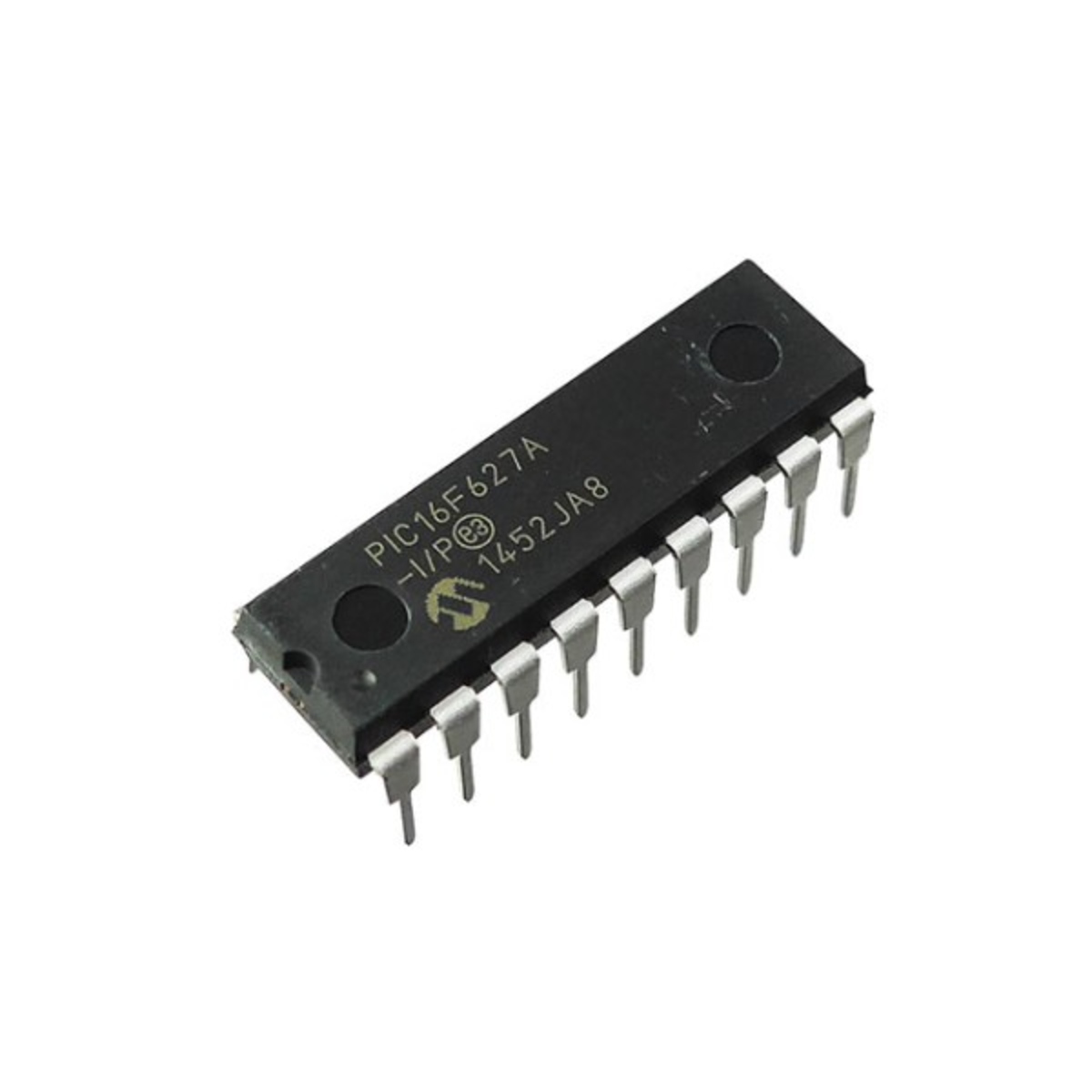
PIC16F627A-I/P 8-Bit Flash Microcontroller with Dual Comparators DIP-18 (PIC16F627A-I/P DIP IC)
The PIC16F627A-I/P is a highly popular and versatile 8-bit Flash-based microcontroller in Microchip’s mid-range family. It serves as a modern, pin-compatible upgrade to the classic PIC16F84A, offering significantly more features in the same 18-pin DIP footprint. It features a powerful RISC architecture with 35 single-word instructions and includes 1.75KB of Flash program memory and 224 bytes of RAM. A key advantage of this IC is its integrated internal 4MHz RC oscillator, which frees up I/O pins and reduces total project cost. It also includes a Capture/Compare/PWM (CCP) module, a Universal Asynchronous Receiver Transmitter (UART), and dual analog comparators, making it a robust all-in-one controller.
This IC is primarily used in automotive security systems, smart home sensors, and handheld electronic devices. It is an essential component for Arduino electronics projects in India for building DIY remote-controlled systems, custom serial communication bridges, and low-power automation projects where a high-performance 18-pin DIP MCU is required.
Key Features
- High-performance RISC CPU with 35 single-word instructions
- Internal 4MHz RC oscillator with programmable calibration
- Dual analog comparators with programmable voltage reference
- Capture/Compare/PWM (CCP) module
- Universal Asynchronous Receiver Transmitter (UART/USART)
- 128 Bytes of high-endurance Data EEPROM (1,000,000 cycles)
- In-Circuit Serial Programming (ICSP) via two pins
- Low-power NanoWatt technology for extended battery life
- Programmable Brown-out Reset (BOR) and Power-on Reset (POR)
- 16 bidirectional I/O pins with individual direction control
Specifications
- IC Type = 8-Bit Flash Microcontroller
- Program Memory = 1.75KB (1024 Words)
- Data RAM = 224 Bytes
- Data EEPROM = 128 Bytes
- Speed = 4MHz (Internal) / 20MHz (External)
- I/O Pins = 16 (Ports A and B)
- Supply Voltage = 2.0V to 5.5V
- Current Sink/Source = 25mA
- Package Type = PDIP-18
- Number of Pins = 18
- Mounting Type = Through-Hole
- Operating Temperature = -40 to 85 degrees Celsius
Interfaces
- PIN 1, 2 (RA2, RA3) = Port A I/O / Comparator Inputs / Vref
- PIN 3 (RA4/T0CKI) = Port A I/O / Timer 0 Clock Input
- PIN 4 (MCLR/VPP) = Master Clear / Programming Voltage
- PIN 5 (VSS) = Ground (0V)
- PIN 6 to 13 (RB0 to RB7) = 8-Bit Port B / UART (TX/RX) / CCP1 / Interrupts
- PIN 14 (VDD) = Positive Supply Voltage (5V)
- PIN 15, 16 (OSC2, OSC1) = Oscillator Output/Input
- PIN 17, 18 (RA0, RA1) = Port A I/O / Comparator Inputs