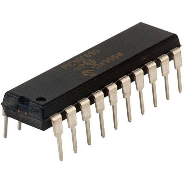
PIC16F690-I/P 8-Bit Flash Microcontroller with ECCP and 12-Channel ADC DIP-20 (PIC16F690-I/P DIP IC)
The PIC16F690-I/P is a highly versatile, 8-bit Flash-based microcontroller from Microchip's mid-range family, offering a "big feature set in a small package." It features a powerful RISC architecture with 35 single-word instructions and is equipped with 7KB of Flash program memory, 256 bytes of RAM, and 256 bytes of high-endurance EEPROM. Key highlights include a 12-channel 10-bit Analog-to-Digital Converter (ADC), an Enhanced Capture/Compare/PWM (ECCP) module with half and full-bridge support, and a Synchronous Serial Port (SSP) that handles SPI and I2C. With its precision internal oscillator and broad communication capabilities, it is a flagship choice for 20-pin mid-range applications.
This IC is primarily used in brushless DC motor control, industrial sensing nodes, and handheld medical devices. It is an extremely popular component for Arduino electronics projects in India for building DIY robot controllers, multi-channel data acquisition systems, and smart home automation hubs that require a high number of analog inputs and advanced PWM capabilities in a standard 20-pin DIP footprint.
Key Features
- High-performance RISC CPU with 35 single-word instructions
- 12-channel 10-bit Analog-to-Digital Converter (ADC)
- Enhanced Capture/Compare/PWM (ECCP) with PWM steering and dead-band control
- 256 Bytes of high-endurance Data EEPROM (1,000,000 cycles)
- Integrated Synchronous Serial Port (SSP) with SPI and I2C (Master/Slave)
- Enhanced USART module (supports RS-485, RS-232, and LIN 2.0)
- Precision internal oscillator (8MHz to 31kHz, software selectable)
- Ultra-low power NanoWatt technology with ULPWU (Ultra Low-Power Wake-Up)
- Two analog comparators with a programmable voltage reference
- 18 bidirectional I/O pins with high current source/sink (25mA)
Specifications
- IC Type = 8-Bit Flash Microcontroller with ECCP
- Program Memory = 7KB (4096 Words)
- Data RAM = 256 Bytes
- Data EEPROM = 256 Bytes
- ADC Resolution = 10-Bit (12 Channels)
- Maximum Speed = 20MHz (External) / 8MHz (Internal)
- I/O Pins = 18 (plus 1 input-only pin)
- Supply Voltage = 2.0V to 5.5V
- Current Sink/Source = 25mA
- Package Type = PDIP-20
- Number of Pins = 20
- Mounting Type = Through-Hole
- Operating Temperature = -40 to 85 degrees Celsius
Interfaces
- PIN 1 (VDD) = Positive Supply Voltage (5V)
- PIN 2 (RA5/T1CKI/OSC1/CLKIN) = Port A I/O / Timer 1 Clock Input
- PIN 3 (RA4/AN3/T1G/OSC2/CLKOUT) = Port A I/O / Analog Input 3
- PIN 4 (RA3/MCLR/VPP) = Input Only / Master Clear / Programming Voltage
- PIN 5 (RC5/RX/DT) = Port C I/O / USART Receive / Data
- PIN 6 (RC4/TX/CK) = Port C I/O / USART Transmit / Clock
- PIN 7 (RC3/AN7/C12IN3-) = Port C I/O / Analog Input 7
- PIN 8 (RC6/AN8/SS) = Port C I/O / Analog Input 8 / SPI Slave Select
- PIN 9 (RC7/AN9/SDO) = Port C I/O / Analog Input 9 / SPI Data Out
- PIN 10 (RB7/TX/CK) = Port B I/O / Alternate USART TX
- PIN 11 (RB6/SCK/SCL) = Port B I/O / SPI Clock / I2C Clock
- PIN 12 (RB5/AN11/RX/DT) = Port B I/O / Analog Input 11 / Alternate USART RX
- PIN 13 (RB4/AN10/SDI/SDA) = Port B I/O / Analog Input 10 / SPI Data In / I2C Data
- PIN 14 (RC2/AN6/C12IN2-/P1D) = Port C I/O / Analog Input 6 / PWM Output D
- PIN 15 (RC1/AN5/C12IN1-/P1C) = Port C I/O / Analog Input 5 / PWM Output C
- PIN 16 (RC0/AN4/C2IN+/P1B) = Port C I/O / Analog Input 4 / PWM Output B
- PIN 17 (RA2/AN2/T0CKI/INT/COUT) = Port A I/O / Analog Input 2 / Comparator Out
- PIN 18 (RA1/AN1/VREF/ICSPCLK) = Port A I/O / Analog Input 1 / Programming Clock
- PIN 19 (RA0/AN0/ULPWU/ICSPDAT) = Port A I/O / Analog Input 0 / Programming Data
- PIN 20 (VSS) = Ground (0V)