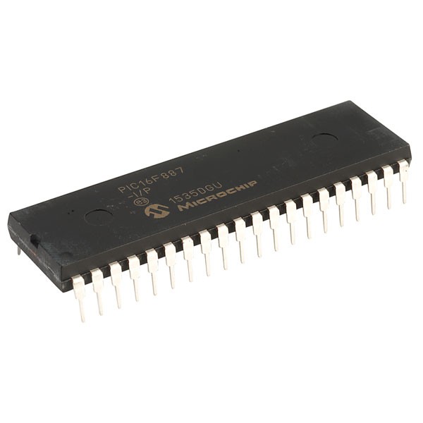
PIC16F887-I/P 8-Bit Flash Microcontroller with 14-Channel ADC DIP-40 (PIC16F887-I/P DIP IC)
The PIC16F887-I/P is a flagship 8-bit Flash-based microcontroller from Microchip's enhanced mid-range series (PIC16F88x). Housed in a standard 40-pin DIP package, it is designed to be the modern, feature-rich successor to the classic PIC16F877A. It features a powerful RISC architecture with 35 single-word instructions and offers 14KB of Flash program memory, 368 bytes of RAM, and 256 bytes of high-endurance EEPROM. Key hardware upgrades include a 14-channel 10-bit Analog-to-Digital Converter (ADC), dual Enhanced Capture/Compare/PWM (ECCP) modules, and a precision internal oscillator (up to 8MHz). With its high I/O count, advanced NanoWatt power-saving technology, and versatile communication interfaces, it is a premier choice for complex, high-performance embedded systems.
This IC is the preferred choice for professional prototyping and engineering education in India. It is a highly popular component for Arduino-style electronics projects for building DIY industrial automation controllers, complex robotics, multi-sensor smart home hubs, and advanced solar power management systems that require a high pin count and precise analog sensing in a 40-pin DIP footprint.
Key Features
- High-performance RISC CPU with 35 single-word instructions
- 14-channel 10-bit Analog-to-Digital Converter (ADC)
- 14KB Flash program memory for large, multi-functional codebases
- 256 Bytes of high-endurance Data EEPROM (1,000,000 cycles)
- Dual Enhanced Capture/Compare/PWM (ECCP) with PWM steering and dead-band control
- Enhanced USART (EUSART) module supporting RS-485, RS-232, and LIN 2.0
- Master Synchronous Serial Port (MSSP) supporting SPI and I2C (Master/Slave)
- Internal oscillator block with 8 selectable frequencies (31kHz to 8MHz)
- Ultra-low power NanoWatt technology with ULPWU (Ultra Low-Power Wake-Up)
- 35 bidirectional I/O pins with high current source/sink (25mA)
Specifications
- IC Type = 8-Bit Flash Microcontroller
- Program Memory = 14KB (8192 Words)
- Data RAM = 368 Bytes
- Data EEPROM = 256 Bytes
- ADC Resolution = 10-Bit (14 Channels)
- Maximum Speed = 20MHz (External) / 8MHz (Internal)
- I/O Pins = 35 (Ports A, B, C, D, and E)
- Supply Voltage = 2.0V to 5.5V
- Current Sink/Source = 25mA
- Package Type = PDIP-40
- Number of Pins = 40
- Mounting Type = Through-Hole
- Operating Temperature = -40 to 85 degrees Celsius
Interfaces
- PIN 1 (RE3/MCLR/VPP) = Master Clear / Programming Voltage
- PIN 2 to 7 (RA0 to RA5) = Port A / Analog Inputs 0-5
- PIN 8 to 10 (RE0 to RE2) = Port E / Analog Inputs 5-7
- PIN 11, 32 (VDD) = Positive Supply Voltage (5V)
- PIN 12, 31 (VSS) = Ground (0V)
- PIN 13, 14 (OSC1, OSC2) = External Crystal/Oscillator Inputs
- PIN 15 to 18, 23 to 26 (RC0 to RC7) = Port C / Timers / ECCP / EUSART / SPI / I2C
- PIN 19 to 22, 27 to 30 (RD0 to RD7) = 8-Bit Port D / PWM Outputs
- PIN 33 to 40 (RB0 to RB7) = 8-Bit Port B / Analog Inputs 8-13 / ICSP