AD620 Signal Adjustable Amplifier Module (DC Microvolt & Millivolt Instrumentation Amplifier)
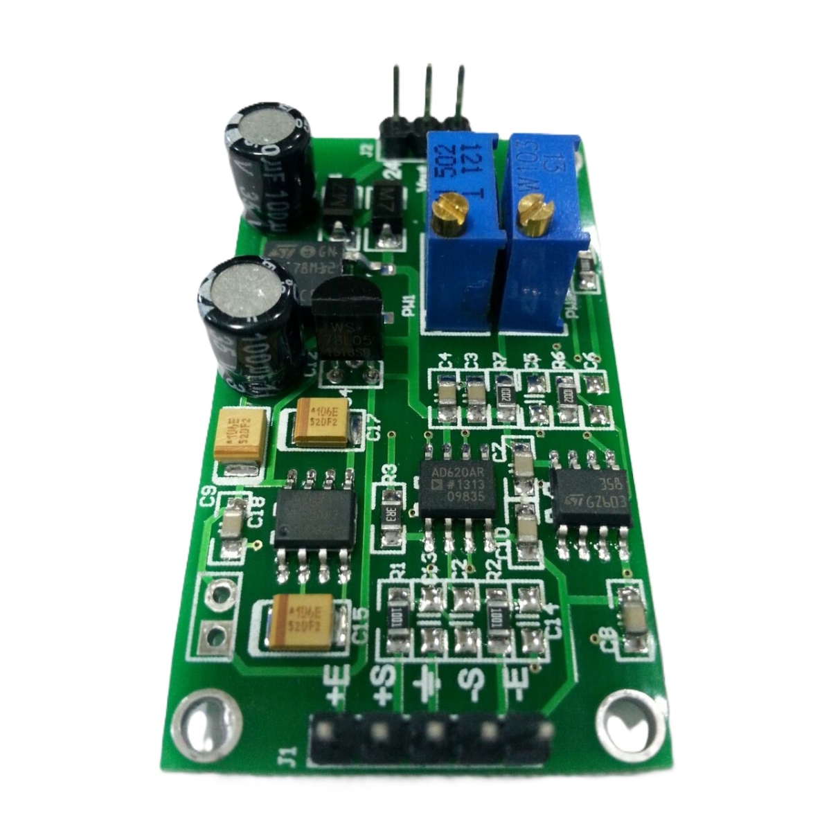
The AD620 Signal Adjustable Amplifier Module is a precision instrumentation amplifier designed to amplify low-level DC differential signals in the microvolt and millivolt range. Based on the AD620 instrumentation amplifier IC, it offers high input impedance, low noise, excellent common-mode rejection, and adjustable gain for accurate signal conditioning. The module is ideal for amplifying outputs from strain gauges, load cells, biomedical sensors, thermocouples, and other precision analog sensors before analog-to-digital conversion in embedded systems.
Key Features -
• Based on the AD620 precision instrumentation amplifier IC
• Amplifies microvolt and millivolt differential signals
• Adjustable gain using an external resistor
• High input impedance for minimal sensor loading
• Low noise and high common-mode rejection performance
• Suitable for precision signal conditioning applications
• Compact PCB module for easy integration
• Compatible with Arduino, ESP32, STM32, PIC, AVR, and other microcontrollers
• Supports flexible power supply configurations using onboard jumper caps
• Ideal for instrumentation, biomedical, and industrial measurement systems
Specifications -
• Product type - Instrumentation Amplifier Module
• Main IC / Chipset - AD620
• Operating voltage - 3.3V to 12V DC (Typical)
• Gain - Adjustable via External Resistor
• Input signal type - Differential Microvolt / Millivolt Signals
• Bandwidth - Suitable for Low-Frequency Signals
• Noise performance - Low Noise Design
• Output signal - Amplified Analog Voltage
• Package / Mounting type - Compact PCB Module
Applications -
• Load cell and weighing systems
• Strain gauge signal amplification
• Biomedical signal acquisition such as ECG and EMG
• Thermocouple and bridge sensor interfacing
• Industrial instrumentation and process monitoring
• Precision data acquisition systems
• Arduino and embedded analog signal conditioning
• Laboratory testing and sensor evaluation
Important Notes -
• The module is supplied with two jumper caps installed separately.
• When using a 5V DC power supply, install both jumper caps to bridge the designated connections before powering the module.
• When using a 7V to 24V DC power supply, do not install the jumper caps, as doing so may permanently damage the circuit board.
• Verify the power supply voltage and jumper configuration before use to ensure safe operation.