
AD8232 Heart Rate Monitor Hookup Guide
₹ 814.20 (Inclusive of 18.00% GST)
Base Price: ₹ 690.00 | GST (18.00%): ₹ 124.20
Out of Stock
Secure payments powered by Razorpay


Pune Store Pickup – Free
Order before 5 PM • Ready in approx. 2 hours
Collect upto 7:30 PM (Mon – Sat)
Collect upto 7:30 PM (Mon – Sat)
Dispatch from Pune
Orders before 3 PM: Same day dispatch
Orders after 3 PM: Next day dispatch
(No dispatch on Sunday)
Orders after 3 PM: Next day dispatch
(No dispatch on Sunday)
Buying in bulk?
Secure Payments100% safe and trusted
GST InvoiceWith every order
Wide Product RangeComponents, modules, tools and more
Product SupportQuick assistance via email
AD8232 Heart Rate Monitor Hookup Guide
The AD8232 Heart Rate Monitor Module is an integrated signal conditioning block designed for ECG and heart rate monitoring applications. It extracts amplifies and filters small biopotential signals from the body and provides an analog output suitable for microcontrollers.
This guide explains how to connect the AD8232 module to common development boards such as Arduino and ESP32 for basic heart rate monitoring and ECG waveform observation.
Pin Description
- 3.3V = Power supply input
- GND = Ground reference
- OUTPUT = Analog ECG signal output
- LO+ = Lead off detection positive
- LO- = Lead off detection negative
- SDN = Shutdown control input
- RA = Right arm electrode input
- LA = Left arm electrode input
- RL = Right leg electrode input
Basic Wiring With Arduino
AD8232 Module to Arduino Connection
- 3.3V = 3.3V
- GND = GND
- OUTPUT = A0
- LO+ = D10
- LO- = D11
Note
Use only 3.3V supply. Do not connect to 5V.
Electrode Placement
For basic heart rate monitoring
- RA electrode = Right arm
- LA electrode = Left arm
- RL electrode = Right leg reference
Proper skin contact improves signal stability.
Related Products
 6x4.5 Inch 6045 6045R Propeller Pair CW CCW (Drone Propeller Set)
E-496
₹ 59.00 (Incl. GST)
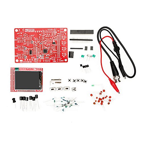 JYE Tech DSO138 DIY Digital Oscilloscope Kit 13803K (SMD Soldered Version with Housing)
E-479
₹ 1,652.00 (Incl. GST)
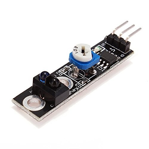 KY-033 Infrared Line Tracking Sensor Module (Black & White Line Detection Module)
E-478
₹ 88.50 (Incl. GST)
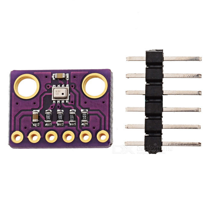 BMP280 Digital Barometric Pressure Sensor Module (I2C/SPI Pressure & Temperature Sensor)
E-477
₹ 41.30 (Incl. GST)
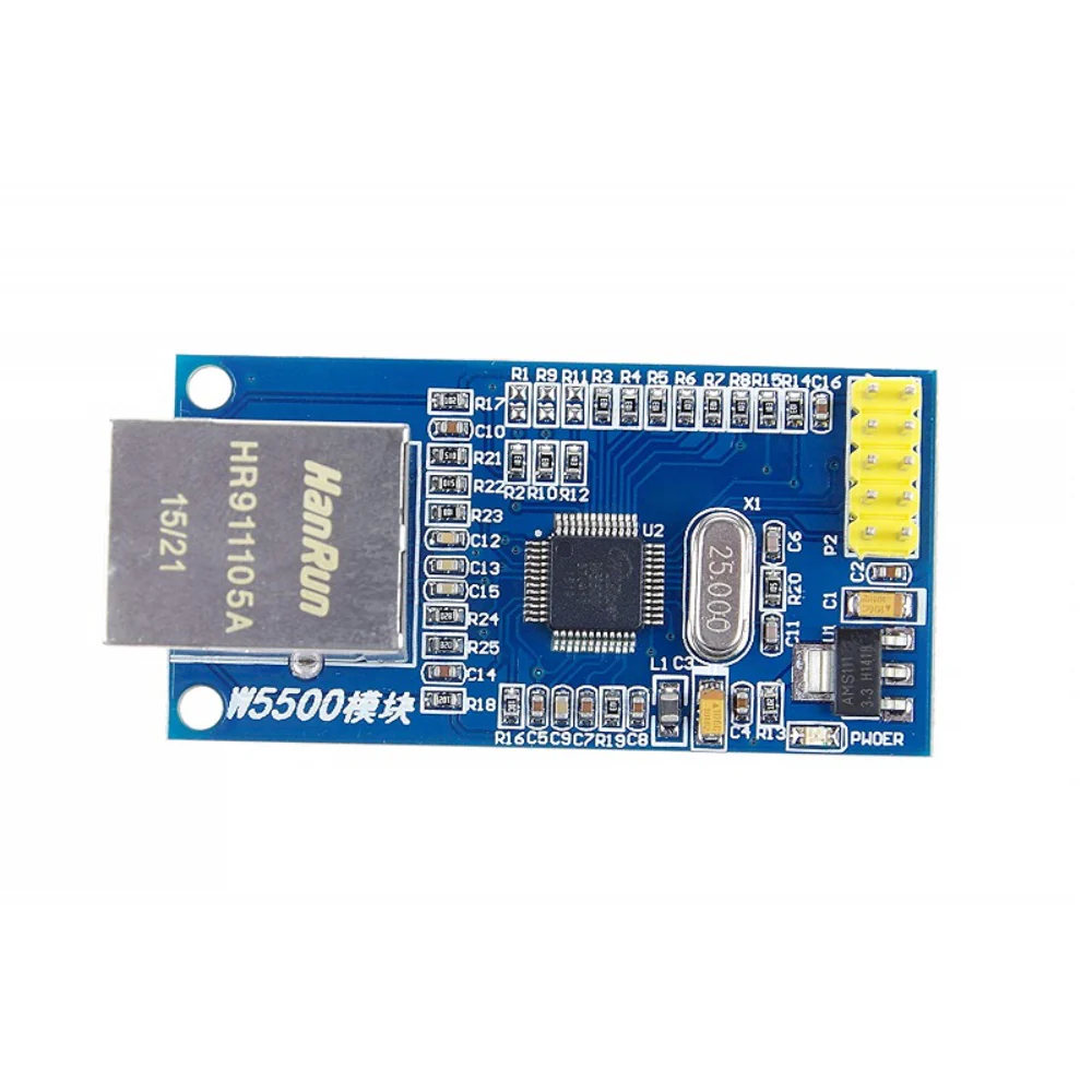 SPI to Ethernet W5500 Hardware TCP/IP Network Module (10/100Mbps Ethernet Interface Board)
E-476
₹ 460.20 (Incl. GST)
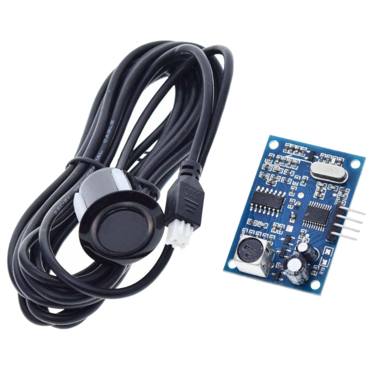 JSN-SR04 Waterproof Ultrasonic Obstacle Sensor Module with Probe (40kHz Distance Measuring Sensor)
E-475
₹ 519.20 (Incl. GST)
 5045 5x4.5 Propeller CW/CCW Pair (5 Inch Drone Propellers for Brushless Motors)
E-495
₹ 59.00 (Incl. GST)
 MCP2515 CAN Bus Module with TJA1050 Transceiver (SPI CAN Controller for Arduino)
E-466
₹ 324.50 (Incl. GST)
 K0730S-12V Push Pull Solenoid Electromagnetic Actuator 12V DC (Linear Solenoid)
E-499
₹ 649.00 (Incl. GST)
 SOP SOIC-8 IC Test Clip Programmer Clamp 1.27mm DIP8 Adapter (In-Circuit Programming Clip)
E-468
₹ 206.50 (Incl. GST)